
Projection and actuation device for a walking stabilizer

a technology of projection device and actuation device, which is applied in the direction of gymnastic exercise, sport apparatus, transportation and packaging, etc., can solve the problems of not fully activating projection device and generating visual stimulus, so as to prevent accidental activation of projection device, reduce the frequency of battery replacement, and save battery power

Active Publication Date: 2009-02-03
MILLER JONATHAN JAY
View PDF9 Cites 64 Cited by
  • Summary
  • Abstract
  • Description
  • Claims
  • Application Information

AI Technical Summary

Benefits of technology

"The present invention is a device that helps people with Parkinson's disease and strokes to improve their walking by using a two pole series switch circuit in tandem with a braking mechanism. The device has a visual cue that is triggered when the user squeezes the brakes, making it easier for them to activate the device. The invention can be used for rehabilitation and to increase stride length of patients with walking disorders. The device can be activated by pressing a button or by using a capacitive sensor or a strain-pressure sensor. The technical effect of the invention is to provide a more effective tool for people with mobility issues to improve their walking."

Problems solved by technology

However, the projection device does not fully activate and generate the visual stimulus until the user releases the brakes from the walking stabilizer wheels, by either depressing one or both dual action hand brake levers or the backrest-middle brake bar.

Method used


Image

  • Projection and actuation device for a walking stabilizer
  • Projection and actuation device for a walking stabilizer
  • Projection and actuation device for a walking stabilizer

Examples


first embodiment

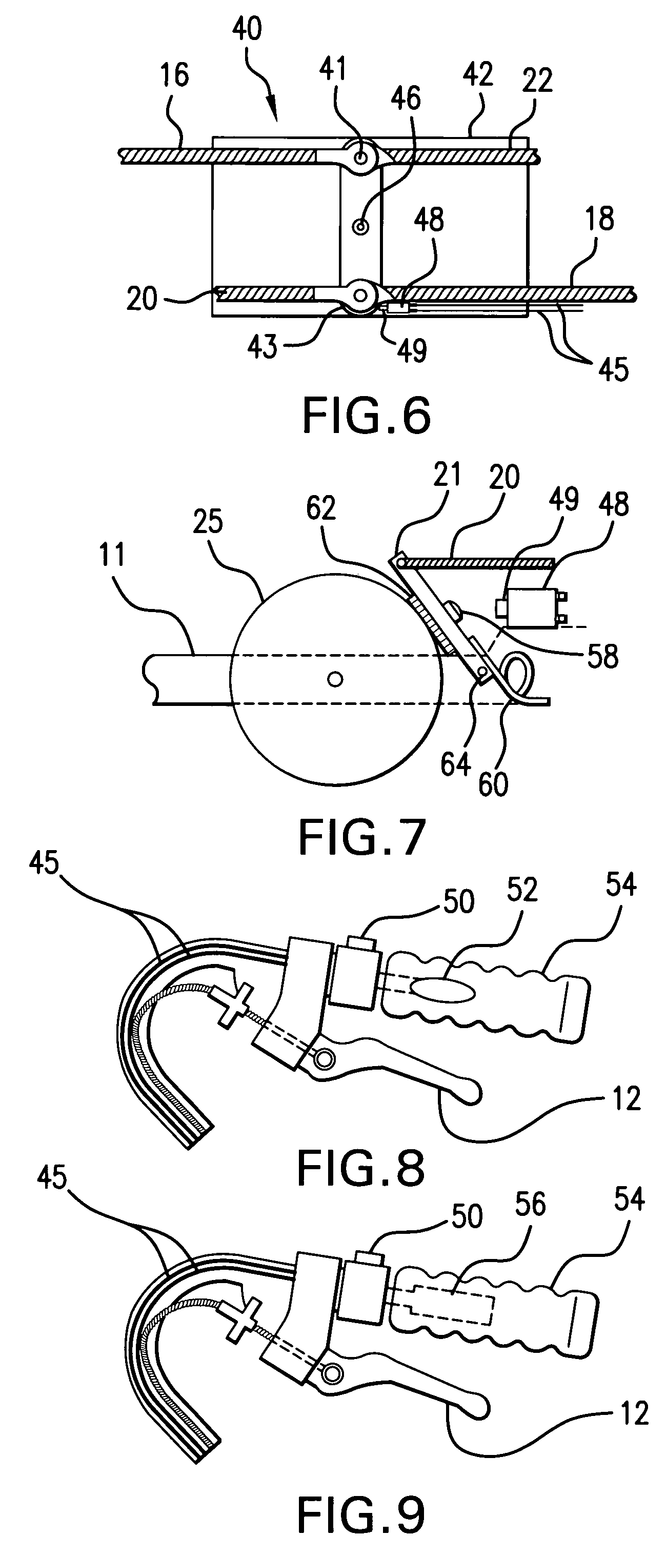
[0032]Additional variations of the first embodiment allow for the placement of activation switch 48 in the vicinity of the lower brake assembly 21 or 23, or other moving parts of the braking mechanism, where the action of disengaging the brake assembly 21 or 23 depresses the contact portion 49 of activation switch 48. FIG. 7 illustrates the placement of activation switch 48 on a section of the U-shaped base 11 next to lower brake assembly 21. When the rolling walking stabilizer 10 is in a stationary mode, biasing spring 60 pushes the lower brake assembly 21 that is pivotally connected by pin 64 to the U-shaped base toward wheel 25 resulting in brake pad 62 being in contact with wheel 25. In the instance when the walking stabilizer is free for movement, lower brake cable 20 pulls on the lower brake assembly 21 with enough tension to overcome the force of the biasing spring 60 and disengages brake pad 62 from wheel 25. When the lower brake assembly 21 is disengaged from the wheel 25, ...

third embodiment

[0037]In a third embodiment, shown in FIG. 8, a pressure sensitive switch 56 is contained within hand grip 54. When the user squeezes and / or places downward pressure on hand grip 54, the pressure sensitive switch is activated. If the projection device option has been selected via regulator switch 50, and the pressure sensitive switch 56 is activated, the projection device will be turned on.


PUM


Abstract

A walking stabilizer equipped to combat the effects of akinesia paradoxica by employing a novel method and device to regulate and actuate a projection instrument which generates a pattern perpendicular to the user's direction of travel. The regulating and actuating device comprises a two pole series switch circuit configuration in tandem with the walking stabilizer's novel dual action braking mechanism. The projection device is only operable when the user concurrently selects its use and when the walker stabilizer is free for movement or in contact with the patient.

Description

FIELD OF INVENTION[0001]The present invention relates to a method and device to regulate and actuate a projection instrument mounted to a walking stabilizer which generates a pattern or line perpendicular to the direction of travel.BACKGROUND AND DESCRIPTION OF THE RELATED ART[0002]A common manifestation of Parkinson's disease or of other related nervous system disorders in a patient is the occurrence of an akinetic episode. A patient who experiences an akinetic episode freezes in place or exhibits a form of start hesitation. The akinetic episodes momentarily may affect the arms, feet or legs; however it is more common for the patient to loose movement in the feet and legs. During an akinetic episode the patient's ability to walk is impaired and is unable to make forward progress. The freezing, formally termed akinesia paradoxica usually lasts for seconds to minutes, but in the extreme can last for hours. The neurologist Joseph Jankovic M.D. fully describes the phenomena of akinesia...

Claims


Application Information

Patent Timeline
Patent Type & Authority Patents(United States)
IPC IPC(8): B62B1/00B62B11/00A45B3/00A45B3/02A61H3/00A63B15/00
CPCA61H3/04A61H2003/046A61H2201/1633
Inventor MILLER, JONATHAN JAY
Owner MILLER JONATHAN JAY
Learn More