Demodulation method and apparatus

a demodulation method and apparatus technology, applied in the field of demodulation techniques, can solve the problems of large hardware resources, high computation load, and occupying significant die spa

Inactive Publication Date: 2009-01-27
AISIN SEIKI KK
View PDF10 Cites 2 Cited by
  • Summary
  • Abstract
  • Description
  • Claims
  • Application Information

AI Technical Summary

Benefits of technology

[0017]According to another aspect of the present invention, a computer readable storage medium storing an executable algorithm, which when executed on a processor performs a method is provided. The method comprises transforming the signal into a modified signal representation in which both amplitude-varying information and frequency-varying information are converted to a uniform representation; and processing the modified signal representation to demodulate the signal based on the uniform representation.

Problems solved by technology

Such circuits involve significant hardware resources, occupy significant die space when implemented in an integrated circuit, and / or have a high computation load in order to implement both types of demodulation in parallel or in series.
Both types of demodulation circuit may perform poorly when demodulating a poor quality or damaged FSK signal in which one of the FSK tones may be of low amplitude such as the tone being close to the noise floor.
Such a signal is difficult to decode by a related art FSK demodulation technique, and would also not be recognised as a true ASK signal.
Such a poor quality FSK signal is not uncommon in remote control applications, because a transmitter will usually be a miniaturized circuit that may be of low cost, low complexity, or have poor operating tolerances or low transmission power.
The problem may be compounded when the signal is transmitted or received in a noisy wireless environment.

Method used


Image

  • Demodulation method and apparatus
  • Demodulation method and apparatus
  • Demodulation method and apparatus

Examples


Embodiment Construction

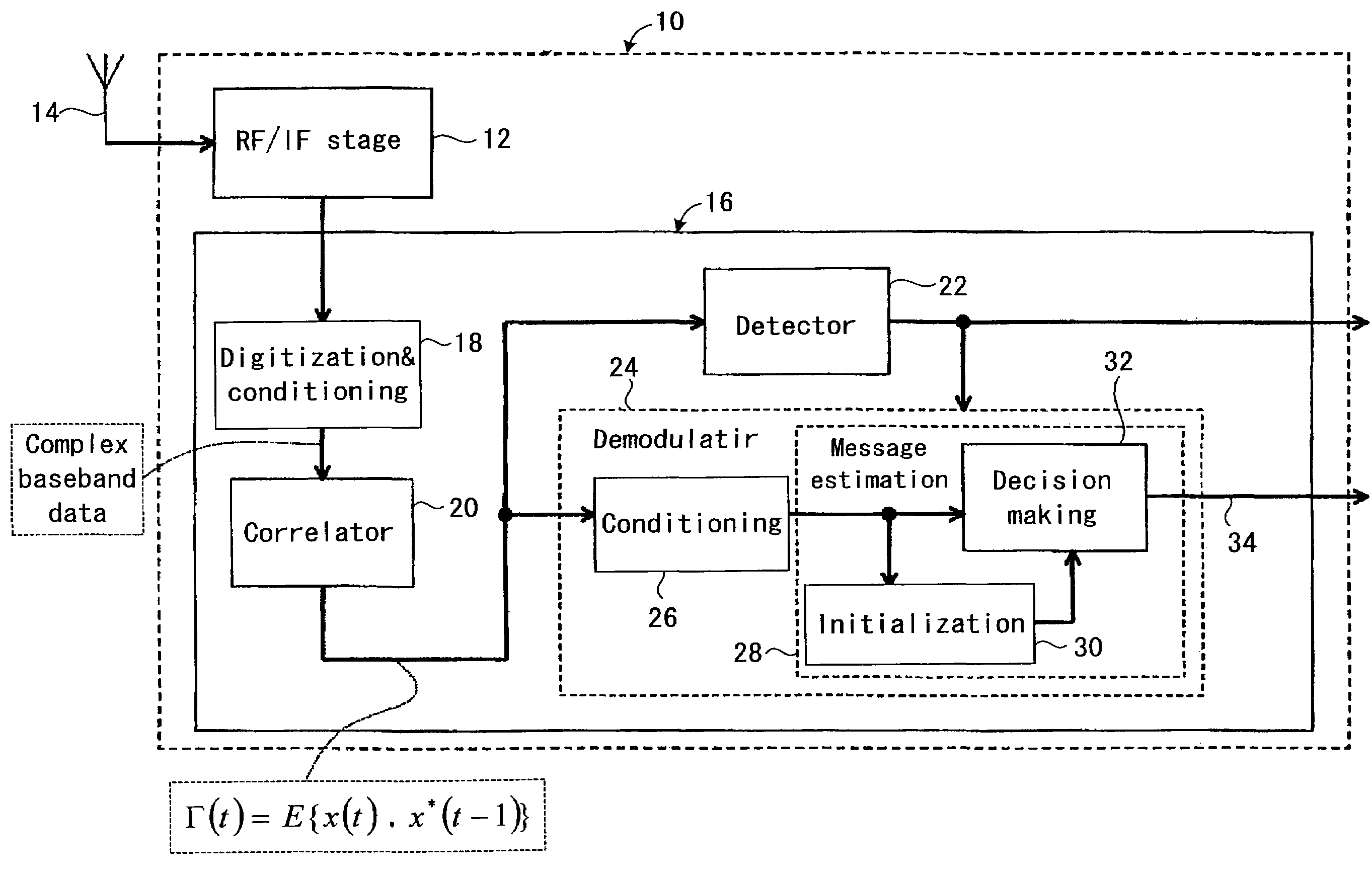
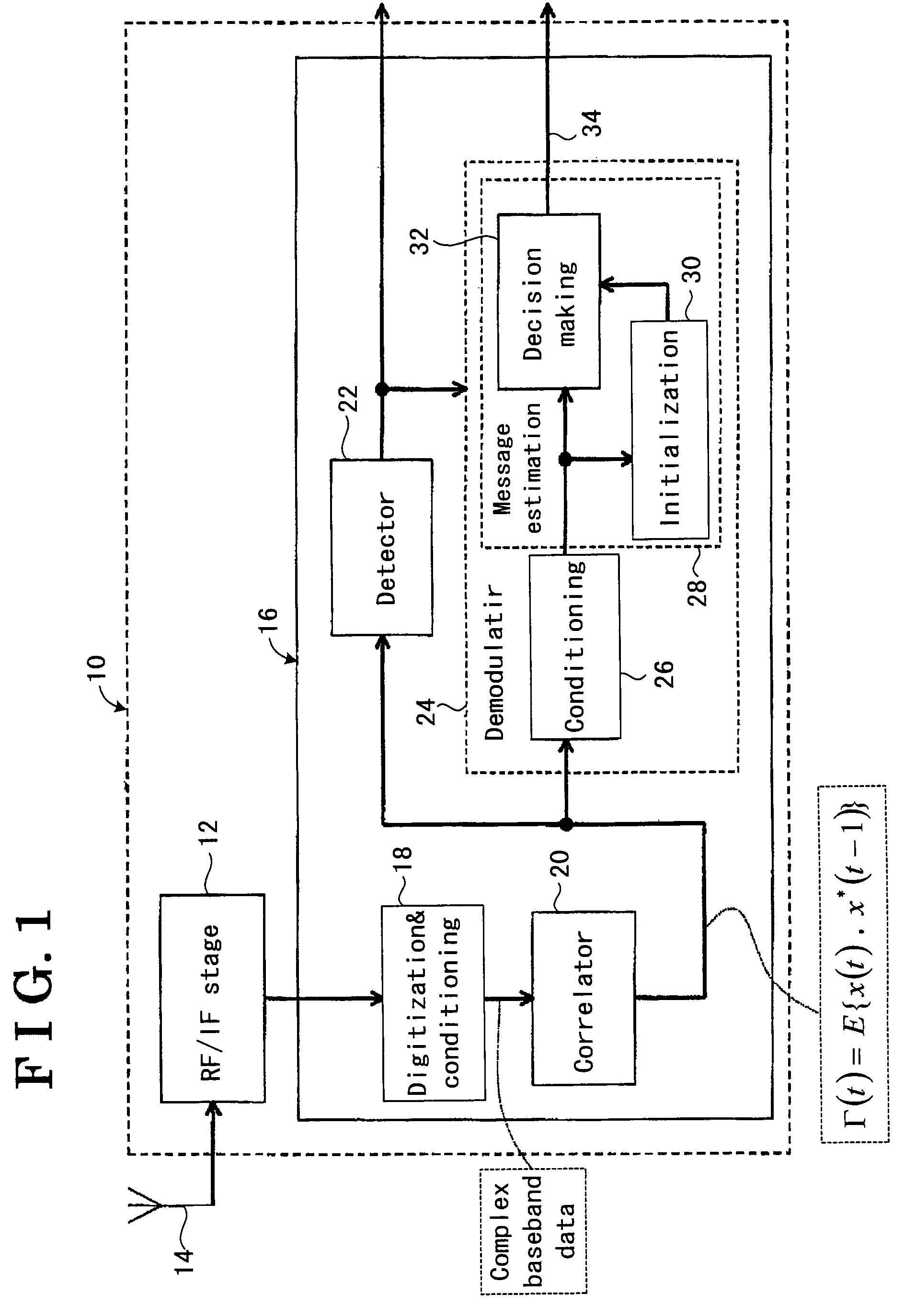
[0028]Referring to FIG. 1, a receiver 10 is illustrated for receiving and demodulating a wireless communication signal. The wireless communication signal may, for example, be an FSK and / or an ASK signal. The receiver 10 may find application in ea vehicle for receiving a remote control signal transmitted from, for example, a remote control key or key-card, or in a building security system, or any other application in which it is desirable to be able to receive and decode a wireless ASK or FSK modulated signal, or a poor quality or damaged FSK signal in which one of the FSK components may have a low amplitude making demodulation difficult or unreliable.

[0029]The receiver 10 comprises an analog Radio Frequency (RF) front-end stage 12 that receives an RF input signal from an antenna 14 and outputs a received signal ready for processing by a processing circuit 16. The RF front-end stage 12 may partly filter the received signal, and down-convert the received signal to an intermediate freq...


PUM


Abstract

A demodulation circuit and method are provided. The demodulation circuit includes a transformation circuit which is configured to transform the received signal into a modified signal representation in which both amplitude-varying information and frequency-varying information are converted to a uniform representation; and a processing circuit which is configured to process the modified signal representation to demodulate the received signal based on the uniform representation. The method includes transforming the signal into a modified signal representation in which both amplitude-varying information and frequency-varying information are converted to a uniform representation; and processing the modified signal representation to demodulate the signal based on the uniform representation.

Description

CROSS-REFERENCE TO RELATED APPLICATION[0001]This application claims priority from French Patent Application No. 0602852 filed on Mar. 31, 2006 in the French Patent Office, the disclosure of which is incorporated herein by reference in its entirety.BACKGROUND TO THE INVENTION[0002]1. Field of the Invention[0003]Methods and apparatuses consistent with the present invention relate to demodulation techniques capable of demodulating a Frequency Shift Keyed (FSK) and / or Amplitude Shift Keyed (ASK) received signal.[0004]2. Description of the Related Art[0005]Related art demodulation circuits that are capable of demodulating both FSK and ASK received signals are generally one of two types. A first type of circuit includes two dedicated demodulators, namely a first dedicated ASK demodulator and a second dedicated FSK demodulator, as well as a control switch for selecting an output of either the FSK or ASK demodulator. Examples of such demodulator circuits are known from CA-A-2306846, EP-A-15...

Claims


Application Information

Patent Timeline
Patent Type & Authority Patents(United States)
IPC IPC(8): H03D1/00H03D3/00H04L27/14
CPCH04L27/0008H04L27/063H04L27/08H04L27/2331H04L27/2334
Inventor AOUINE, TARIKCOUTANT, FREDERICGAETA, MICHEL
Owner AISIN SEIKI KK
Why Eureka
Try Eureka