
Stud system for insulation of concrete structures

a technology of concrete structure and stud system, which is applied in the direction of structural elements, building components, protective foundations, etc., can solve the problems of difficult anchoring of exterior finishing surfaces such as vinyl siding to the exterior surface of the insulated structure, difficult installation of exterior insulation or exterior finishes, and difficulty in transporting and manoeuvre of panels

Inactive Publication Date: 2009-01-27
TARR NEIL
View PDF35 Cites 36 Cited by
  • Summary
  • Abstract
  • Description
  • Claims
  • Application Information

AI Technical Summary

Benefits of technology

"The invention provides a stud for anchoring to a concrete wall and a method for using it to insulate the wall. The stud has a first surface for abutting against the wall, an anchoring system for securing it to the wall, and a lateral web for holding insulation. The method involves placing the stud in proximity to the wall and engaging it with a form tie protruding from the wall. The invention also provides a kit with multiple studs and anchors for attachment to form ties, as well as an opening trim member for securing an insulation surface to an opening in the wall. The kit may also include a corner stud for attachment to a wall corner."

Problems solved by technology

One drawback of rigid insulation panel systems, particularly in the residential construction industry, is the difficulty in anchoring exterior finishing surfaces such as vinyl siding to the exterior surface of the insulated structure.
In addition, the panels are awkward to transport and manoeuvre into place, often requiring the panels to be slid past a retaining system or to be held in place while a retaining system is affixed to the structure.
The studs are removed following curing of the concrete, and are not intended to support exterior insulation or exterior finishes.
In general, ICF's are costly and somewhat fragile, so care must be taken during concrete pouring to prevent bulging, shifting or breakage of the ICF's.
Moreover, the limited strength of ICF's does not allow for proper vibration of the forms to consolidate the concrete, resulting in voids and honeycomb within the finished concrete structure.
The forms are also generally of an awkward size, making transport and storage inconvenient.

Method used


Image

  • Stud system for insulation of concrete structures
  • Stud system for insulation of concrete structures
  • Stud system for insulation of concrete structures

Examples


Embodiment Construction

[0026]Generally, the present invention provides a stud system for attachment to a new or existing concrete structure. The stud is used to support spray foam insulation against the concrete structure, while also providing an attachment surface for securing a finishing product to the structure.

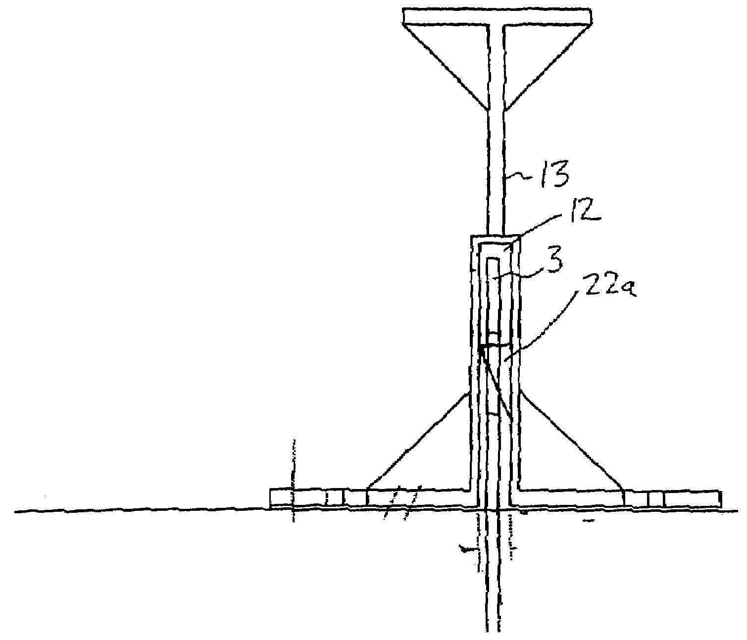
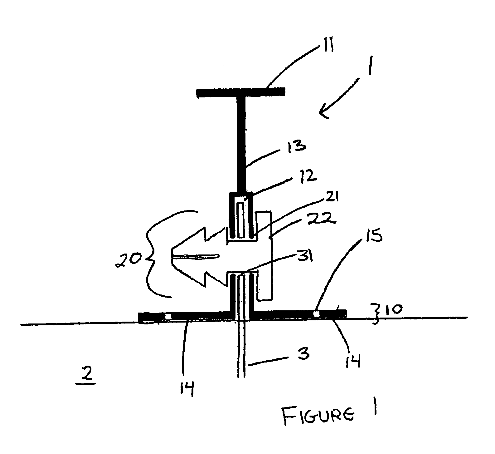
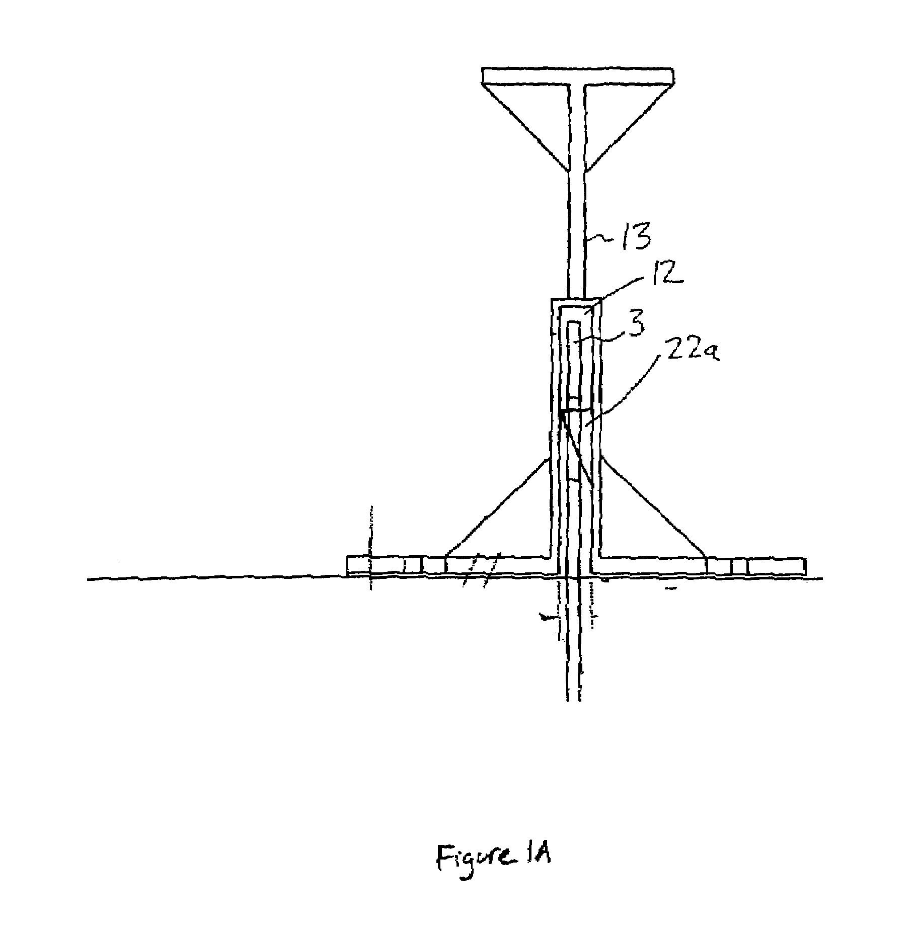
[0027]As shown in the embodiment pictured in FIG. 1, a plastic stud 1, having first and second abutting surfaces 10, 11 and a connecting web 13, is anchored to a concrete wall 2 by an anchoring system 20.

[0028]As is known, form ties 3 generally protrude at regular intervals from either side of the concrete wall 2 following pouring and curing of the concrete. In a preferred embodiment, the stud 1 includes a form tie receptacle 12 for a receiving locking pin 22 through a form tie aperture 31 (collectively an anchoring system 20) for anchoring the stud 1 to the concrete wall 2.

[0029]Concrete forms generally have openings for securing form ties at regular intervals and, accordingly, it is preferred ...


PUM


Abstract

A stud system for supporting spray insulation to an exterior surface of a concrete structure is disclosed. The stud includes a wall abutting surface, and a laterally extending web for promoting adherence of foam insulation when applied to either side of the stud. The stud is attached to the structure by anchoring to one or more form ties protruding from the structure, or by driving fasteners into the structure. The stud also includes a second surface which can be used for attachment of exterior finishes such as vinyl siding or stucco.

Description

FIELD OF THE INVENTION[0001]The present invention relates generally to the insulation of concrete structures. More particularly, the present invention relates to a system for supporting spray foam insulation to an exterior surface of a concrete wall.BACKGROUND OF THE INVENTION[0002]In the construction of concrete structures, such as building foundations and concrete walls, it is often desirable to provide Insulation to the exterior surface of the concrete. In the industry, exterior insulation is usually preferred over interior insulation in that it generally permits complete coverage of the structure without the difficulty of running service conduits such as plumbing and electrical wiring through the insulation, as is required with interior insulation. Moreover, exterior insulation can be completed without entering the structure and does not reduce interior floor space.[0003]Exterior insulation is also advantageous over interior insulation in that it reduces temperature fluctuations...

Claims


Application Information

Patent Timeline
Patent Type & Authority Patents(United States)
IPC IPC(8): E04G17/06E04B2/00E02D27/00E02D27/32E02D31/02E04B1/00E04B1/04E04B1/62E04B1/76E04B5/00E04B7/00E04C1/00E04C2/34E04C3/02E04C3/04E04C5/12E04F13/08E04G21/12
CPCE02D31/02E04B1/762E04F13/0805E04C2003/0491
Inventor TARR, NEIL
Owner TARR NEIL
Learn More