
Robot cleaner, robot cleaning system and method of controlling same

a robot cleaner and cleaning system technology, applied in the direction of automatic control, program control, navigation instruments, etc., can solve the problems of error generation, actual running distance, error generation, etc., and achieve the effect of efficient performing a given amount of work

Inactive Publication Date: 2009-01-27
SAMSUNG GWANGJU ELECTRONICS CO LTD
View PDF31 Cites 94 Cited by
  • Summary
  • Abstract
  • Description
  • Claims
  • Application Information

AI Technical Summary

Benefits of technology

[0003]The present invention has been developed in order to solve the above problems found in the prior art. Accordingly, an object of the present invention is to provide a robot cleaner and a robot cleaning system capable of efficiently performing a given amount of work by recognizing a current position of the robot cleaner more accurately, and by using a position recognition method.

Problems solved by technology

However, in such a position recognition method, errors can occur between the calculated running distance and current position obtained based on the signal detected by the sensor, and the actual running distance and position.
The error is generated by a slip of the wheel or an uneven surface of the area to be cleaned.
As the robot cleaner travels, the position recognition error accumulates.
Therefore, the robot cleaner may deviate from the planned cleaning course due to the accumulated position recognition error.
As a result, there is an occasion where some of the area to be cleaned remains unclean, or the same area is repeatedly cleaned.
Accordingly, the working efficiency of the robot cleaner deteriorates.

Method used


Image

  • Robot cleaner, robot cleaning system and method of controlling same
  • Robot cleaner, robot cleaning system and method of controlling same
  • Robot cleaner, robot cleaning system and method of controlling same

Examples


Embodiment Construction

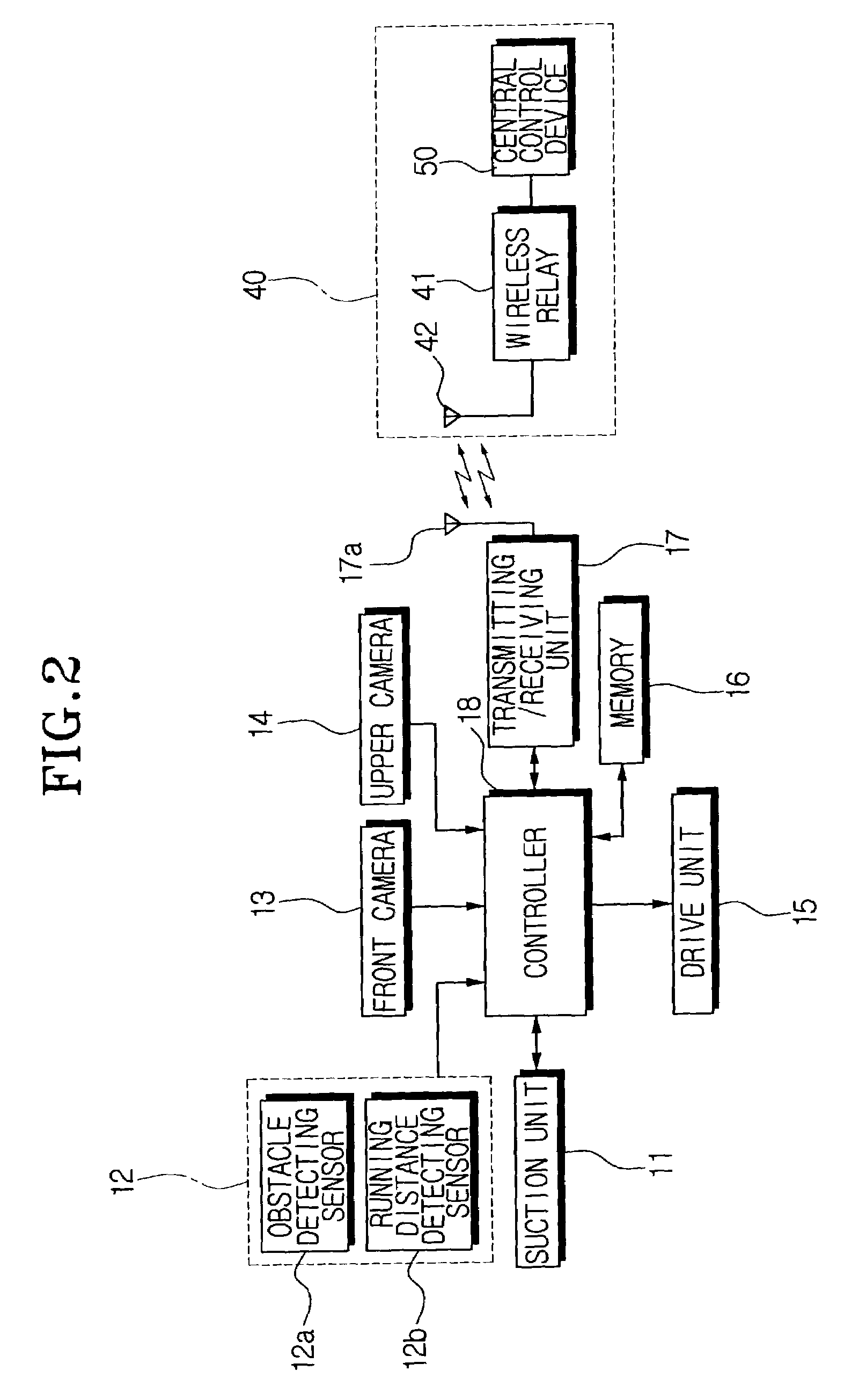
[0019]FIG. 1 is a perspective view showing a robot cleaner according to the present invention, from which a cover is separated. FIG. 2 is a block diagram showing a robot cleaning system according to the present invention.

[0020]Referring to FIGS. 1 and 2, a robot cleaner 10 comprises a suction unit 11, a sensor 12, a front camera 13, an upper camera 14, a drive unit 15, a memory 16, a transmitting / receiving unit 17, and a controller 18. The reference numeral 19 indicates a battery.

[0021]The suction unit 11 is disposed in a body 10a, and draws air therethrough to collect the dust from an opposite cleaning surface. The suction unit 11 is constructed by various methods that will become known. For example, the suction unit 11 comprises a suction motor (not shown) and a dust-collecting chamber for collecting the dust, which is drawn in through a suction port or a suction pipe opposed to the cleaning surface, by the driving of the motor.

[0022]The sensor 12 comprises an obstacle detecting s...


PUM


Abstract

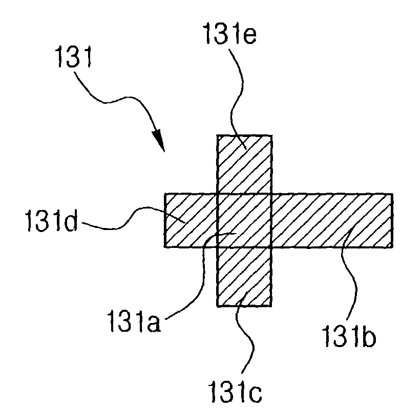
A robot cleaner includes a drive unit for driving a plurality of wheels, a camera disposed in a body for photographing an upper image extending perpendicular to a running direction, a controller for recognizing a position by using position information obtained from a recognition mark formed on a ceiling of a working area that is photographed by the camera, and controlling the drive unit by using the recognized position information to correspond to a target cleaning operation. Accordingly, since the recognition mark for the recognition of a current position of the robot cleaner is formed on a ceiling that has a few changes, the position recognition is performed with more accuracy and the traveling of the robot cleaner to the target work area and a cleaning operation is performed efficiently.

Description

FIELD OF THE INVENTION[0001]The present invention relates to a robot cleaner, a robot cleaning system, and a method of controlling the robot cleaner, and more particularly, to a robot cleaner and a robot cleaning system capable of recognizing a current position of the robot cleaner by making use of an image photographed while the cleaner travels and a position recognition method.BACKGROUND OF THE INVENTION[0002]A typical robot cleaner determines an area to be cleaned by using an ultrasonic wave sensor disposed in its body while traveling along an outline of the area to be cleaned that is enclosed by a wall or an obstacle, and plans a cleaning course to clean the area to be cleaned. Next, the robot cleaner calculates its running distance and current position based on a signal that is detected by a sensor that detects the number of revolutions per minute and the rotation angle of a wheel of the robot cleaner. The robot cleaner drives the wheel to travel along the planned cleaning cour...

Claims


Application Information

Patent Timeline
IPC IPC(8): A47L5/00A47LA47L7/02A47L9/00A47L9/28A47L11/00A47L11/40B25J5/00B25J13/08G05D1/02G05D3/10G06T7/00
CPCA47L9/009G05D1/0234G05D1/0246G05D2201/0215A47L2201/04A47L9/28A47L11/00
Inventor SONG, JEONG-GONLEE, KYOUNG-MUMOON, SEUNG-BINLEE, SANG-YONGKO, JANG-YOUN
Owner SAMSUNG GWANGJU ELECTRONICS CO LTD
Learn More