
Spot color pattern system

a color pattern and color pattern technology, applied in the field of printing documents in a computer environment, can solve the problems of high cost of mistakes or unwanted results, waste of media, and inability to achieve consistent and reproducible methods,

Inactive Publication Date: 2009-01-20
FIERY LLC
View PDF31 Cites 11 Cited by
  • Summary
  • Abstract
  • Description
  • Claims
  • Application Information

AI Technical Summary

Benefits of technology

[0013]The invention provides a spot color pattern system. The system allows users to proof print jobs that require specialized print media on paper-based printers. In addition, the invention allows users to define custom textures that match their specialized print media.
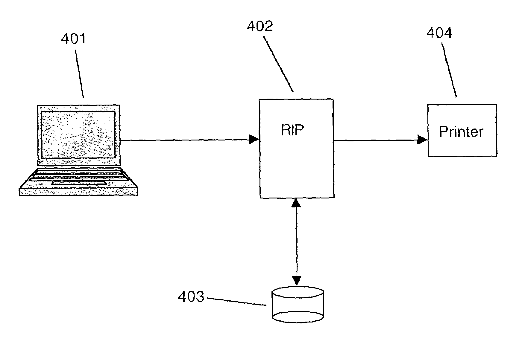
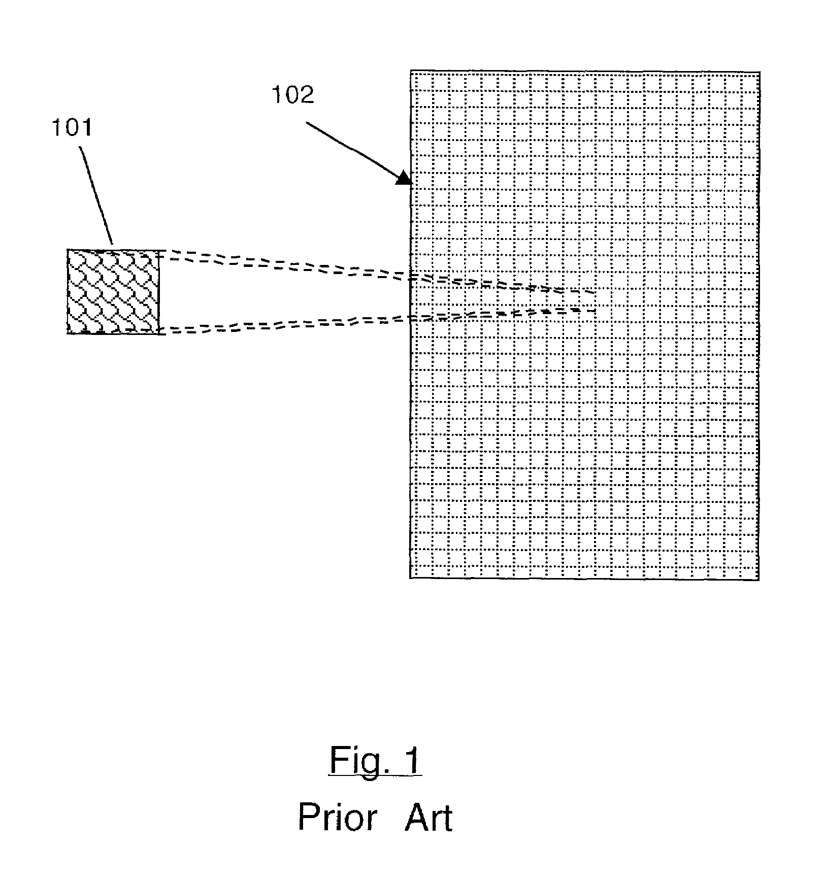
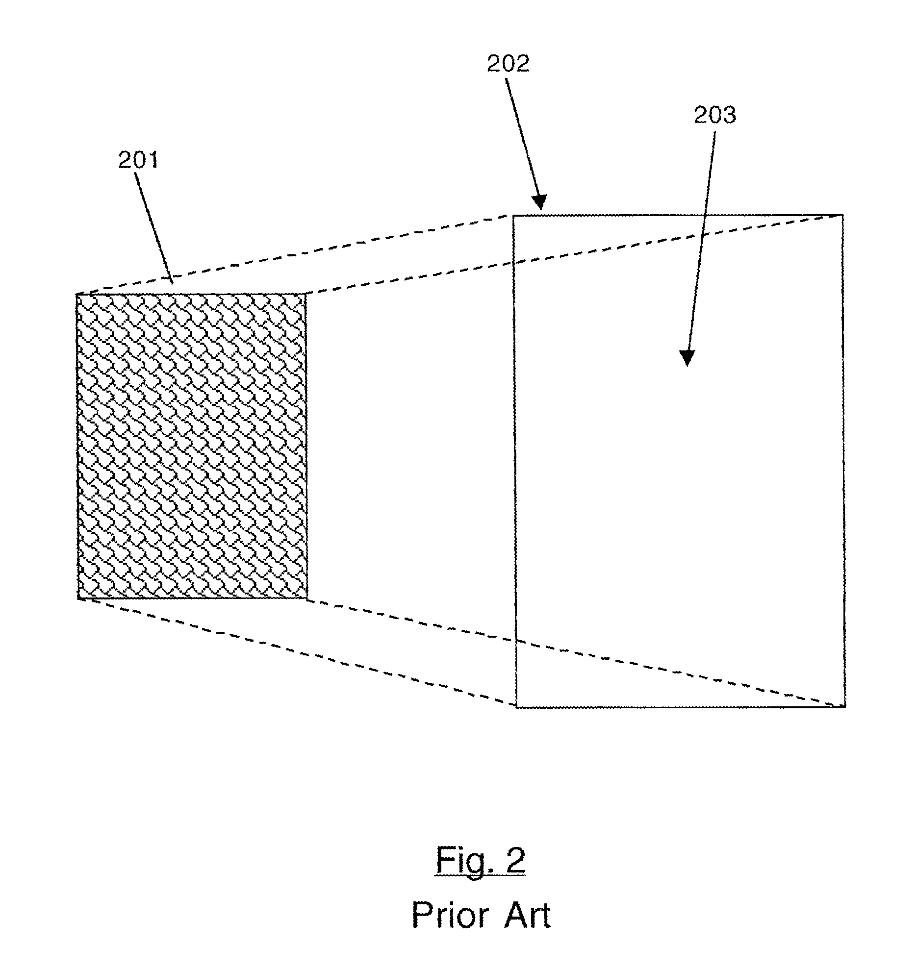
[0015]Print jobs are sent to the RIP. The RIP interprets a spot color pattern name in print job, looks up the spot color in its database, and pulls up the image associated with the spot color pattern name. The RIP adds Postscript pattern code to the print job to draw the pattern and adds other code to perform other tasks, such as mirroring or four-way mirroring to prevent stitches from appearing. The Postscript pattern code paints the spot color across the background or painted into any shape or form on the page of the print job, realistically simulating the final print media.
[0016]The invention allows users to import an image and associate it with a spot color name. A RIP user interface gives the user the ability to create, modify, or delete spot color patterns.

Problems solved by technology

Mistakes or unwanted results are expensive and a waste of the media.
The only drawback is that, using paper-based printers, the printing press customer does not get a realistic reproduction of his print job.
However, these approaches do not allow for a consistent, reproducible method that realistically simulates the printing press customer's specialized print media.
These approaches are very inefficient because they create very large files which extend the download time to the printer and increase processing and memory demands on the printer.

Method used


Image

  • Spot color pattern system
  • Spot color pattern system
  • Spot color pattern system

Examples


Embodiment Construction

[0035]The invention is embodied in a spot color pattern system in a computer environment. A system according to the invention allows users to proof print jobs that require specialized print media on paper-based printers. In addition, the invention allows users to define custom textures that match their specialized print media.

[0036]The invention allows print customers that require specialized print media such as metal or textile to proof their print jobs on paper-based printers by realistically simulating the texture of the actual print media. Spot color patterns combine the concepts of spot colors and patterns and give the user the ability to define custom spot color patterns.

[0037]Image setter / plate setter printers typically require customers to submit CMYK files defining the customer's print jobs. This is because the printing press environment requires print jobs to be in grayscale, CMYK, or spot colors.

[0038]Spot colors are primarily used in the printing industry to achieve very...


PUM


Abstract

A spot color pattern system provides a naming convention that allows the user to name a custom spot color pattern. A Raster Image Processing (RIP) has a database of spot color patterns that are user definable and are patterns which are images of a textile, fabric, metal, etc., that are repeatedly printed across the job. The RIP interprets a spot color pattern name in print job, looks up the spot color in its database, pulls up the image associated with the spot color pattern name, adds Postscript® pattern code to the print job to paint the spot color across the background of the print job, realistically simulating the final print media, and adds other code to perform other tasks, such as mirroring or four-way mirroring to prevent stitches from appearing. A RIP user interface gives the user the ability to create, modify, or delete spot color patterns. The invention also provides a mechanism that allows an application program to access a custom spot color pattern from the RIP.

Description

BACKGROUND OF THE INVENTION[0001]1. Technical Field[0002]The invention relates to printing documents in a computer environment.[0003]More particularly, the invention relates to the specification, storage, and printing of background textures for proof printing in a computer environment.[0004]2. Description of the Prior Art[0005]There are several different levels of end-users in the printing arena. High-end users require a printing press environment using equipment such as offset printers or large-bed inkjet printers to create their final products. Mid to low-end users do not have a need for high quality professional printing. Laser printers and low cost inkjet printers will satisfy for their general needs.[0006]Printing press environment customers have specialized demands. Some customers print their jobs on different materials such as metal, fabrics, and textiles. These customers do not know what the final product looks like until the job is printed on the actual media.[0007]The prin...

Claims


Application Information

Patent Timeline
IPC IPC(8): G06F15/00G06K1/00G06K15/00G06K15/02
CPCG06K15/02H04N1/6052H04N1/54G06K2215/0082G06K2215/0094
Inventor FALK, RICHARD
Owner FIERY LLC
Learn More