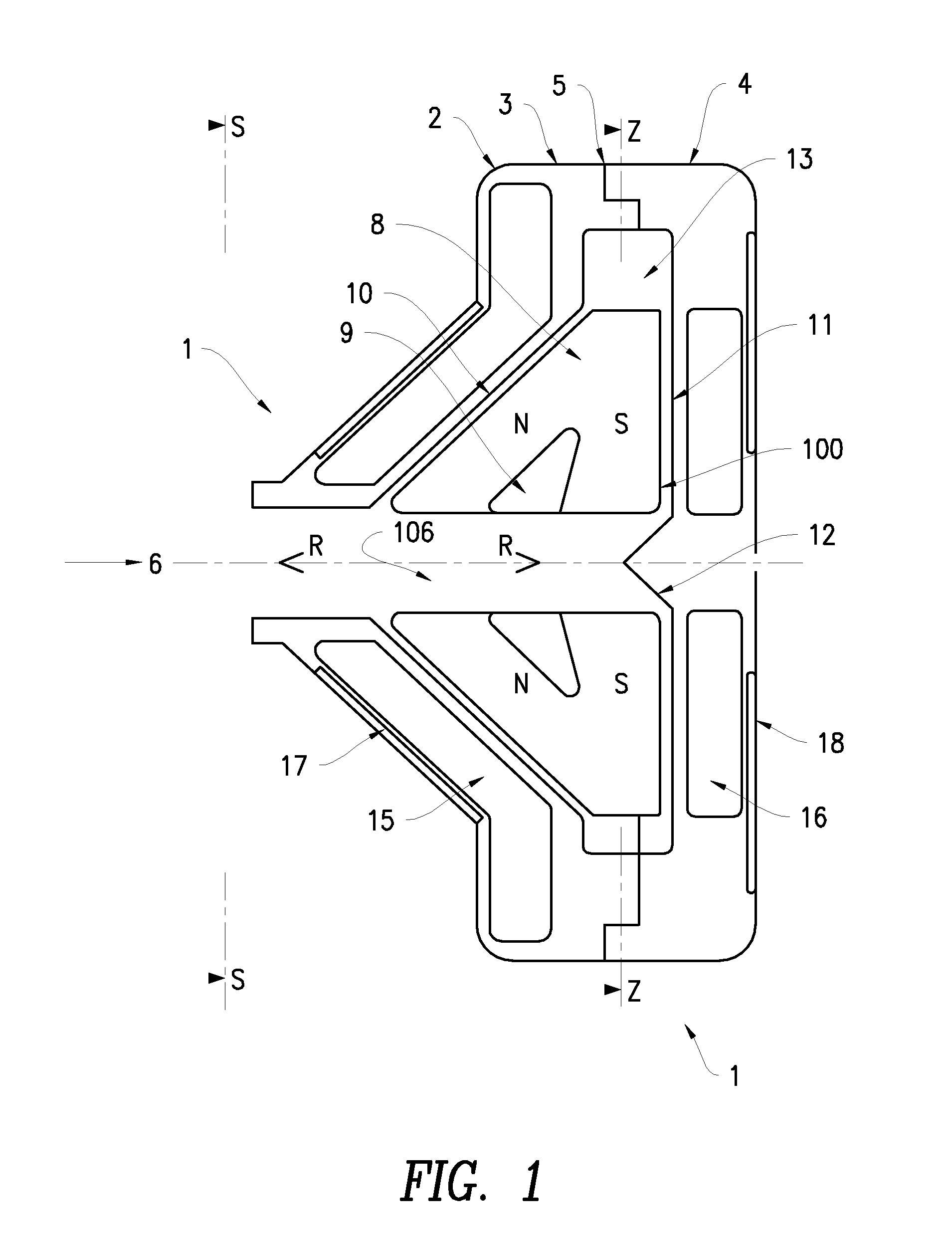
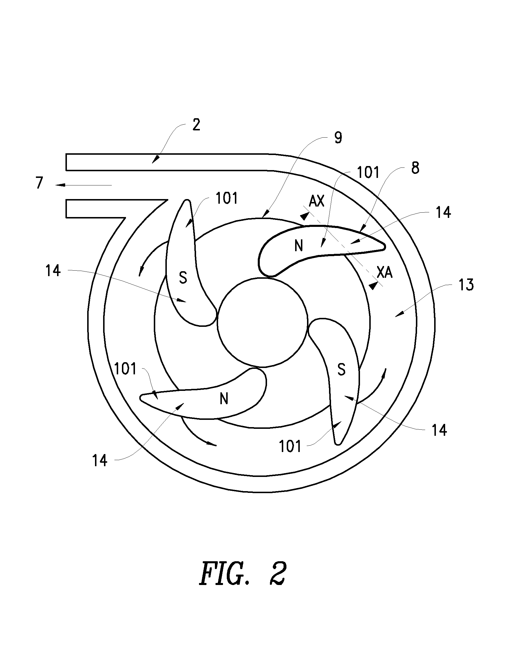
Rotary pump with exclusively hydrodynamically suspended impeller
a technology of hydrodynamic suspension and rotor, which is applied in the direction of piston pumps, positive displacement liquid engines, prosthesis, etc., can solve the problems of rotors providing shaft torque, leaking seals on shafts, and difficulty in meeting these characteristics in a conventional pump configuration
- Summary
- Abstract
- Description
- Claims
- Application Information
AI Technical Summary
Benefits of technology
Problems solved by technology
Method used
Image
Examples
third embodiment
[0118]With reference to FIGS. 7 to 15 inclusive there is shown a further preferred embodiment of the pump assembly 200.
[0119]With particular reference initially to FIG. 7 the pump assembly 200 comprises a housing body 201 adapted for bolted connection to a housing cover 202 and so as to define a centrifugal pump cavity 203 therewithin.
[0120]The cavity 203 houses an impeller 204 adapted to receive magnets 205 within cavities 206 defined within blades 207. As for the first embodiment the blades 207 are supported from a support cone 208.
[0121]Exterior to the cavity 203 but forming part of the pump assembly 200 there is located a body winding 209 symmetrically mounted around inlet 210 and housed between the housing body 201 and a body yoke 211.
[0122]Also forming part of the pump assembly 200 and also mounted external to pump cavity 203 is cover winding 212 located within winding cavity 213 which, in turn, is located within housing cover 202 and closed by cover yoke 214.
[0123]The winding...
fourth embodiment
[0143]With reference to FIG. 18 a further embodiment of the invention is illustrated comprising a plan view of the impeller 300 forming part of a “channel” pump. In this embodiment the blades 301 have been widened relative to the blades 207 of the third embodiment to the point where they are almost sector-shaped and the flow gaps between adjacent blades 301, as a result, take the form of a channel 302, all in communication with axial cavity 303.
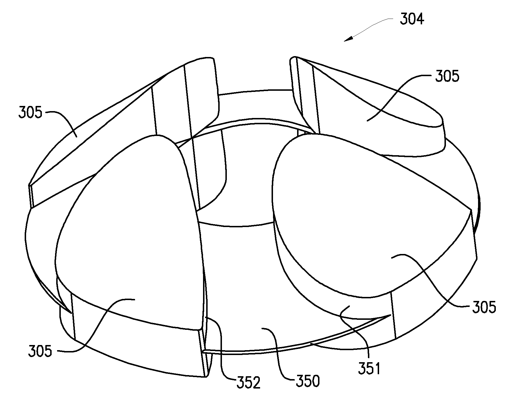
[0144]A further modification of this arrangement is illustrated in FIG. 19 wherein impeller 304 includes sector-shaped blades 305 having curved leading and trailing portions 306, 307 respectively thereby defining channels 308 having fluted exit portions 309.
[0145]As with the first and second embodiments the radial and axial hydrodynamic forces are generated by appropriate profiling of the top and bottom faces of the blades 301, 305 (not shown in FIGS. 18 and 19).
[0146]FIG. 20 illustrates a perspective view of an impeller 304 which follows the...
fifth embodiment
[0147]A fifth embodiment of a pump assembly according to the invention comprises an impeller 410 as illustrated in FIG. 21 where, conceptually, the upper and lower surfaces of the blades of previous embodiments are interconnected by a top shroud 411 and a bottom shroud 412. In this embodiment the blades 413 can be reduced to a very small width as the hydrodynamic behaviour imparted by their surfaces in previous embodiments is now given effect by the profiling of the shrouds 411, 412 which, in this instance, comprises a series of smooth-edged wedges with the leading surface of one wedge directly interconnected to the trailing edge of the next leading wedge 414.
[0148]As for previous embodiments the top shroud 411 is of overall conical shape thereby to impart both radial and axial thrust forces whilst the bottom shroud 412 is substantially planar thereby to impart substantially only axial thrust forces.
[0149]It is to be understood that, whilst the example of FIG. 21 shows the surfaces ...
PUM
 Abstract
Description
Claims
Application Information
 - R&D
- Intellectual Property
- Life Sciences
- Materials
- Tech Scout
- Unparalleled Data Quality
- Higher Quality Content
- 60% Fewer Hallucinations
Browse by: Latest US Patents, China's latest patents, Technical Efficacy Thesaurus, Application Domain, Technology Topic, Popular Technical Reports.
© 2025 PatSnap. All rights reserved.Legal|Privacy policy|Modern Slavery Act Transparency Statement|Sitemap|About US| Contact US: help@patsnap.com


