Dual illumination system for an imaging apparatus and method

a technology of optical imaging and illumination system, applied in the field of optical imaging system, can solve the problems of requiring specialized cooling, presenting particular challenges to the design, and requiring specialized cooling

Inactive Publication Date: 2009-01-06
XENOGEN CORP
View PDF63 Cites 9 Cited by
  • Summary
  • Abstract
  • Description
  • Claims
  • Application Information

AI Technical Summary

Problems solved by technology

Such imaging applications present particular challenges to the design of a box or chamber in which the sample is contained during imaging.
These cameras are generally complex, may require specialized cooling, and are typically fixed to a single location on the top of a specimen chamber.
Due to this static design, one particular challenge to imaging apparatus design is the diverse fluorescent illumination needs required during image capture.

Method used


Image

  • Dual illumination system for an imaging apparatus and method
  • Dual illumination system for an imaging apparatus and method
  • Dual illumination system for an imaging apparatus and method

Examples


Embodiment Construction

[0047]While the present invention will be described with reference to a few specific embodiments, the description is illustrative of the invention and is not to be construed as limiting the invention. Various modifications to the present invention can be made to the preferred embodiments by those skilled in the art without departing from the true spirit and scope of the invention as defined by the appended claims. It will be noted here that for a better understanding, like components are designated by like reference numerals throughout the various figures.

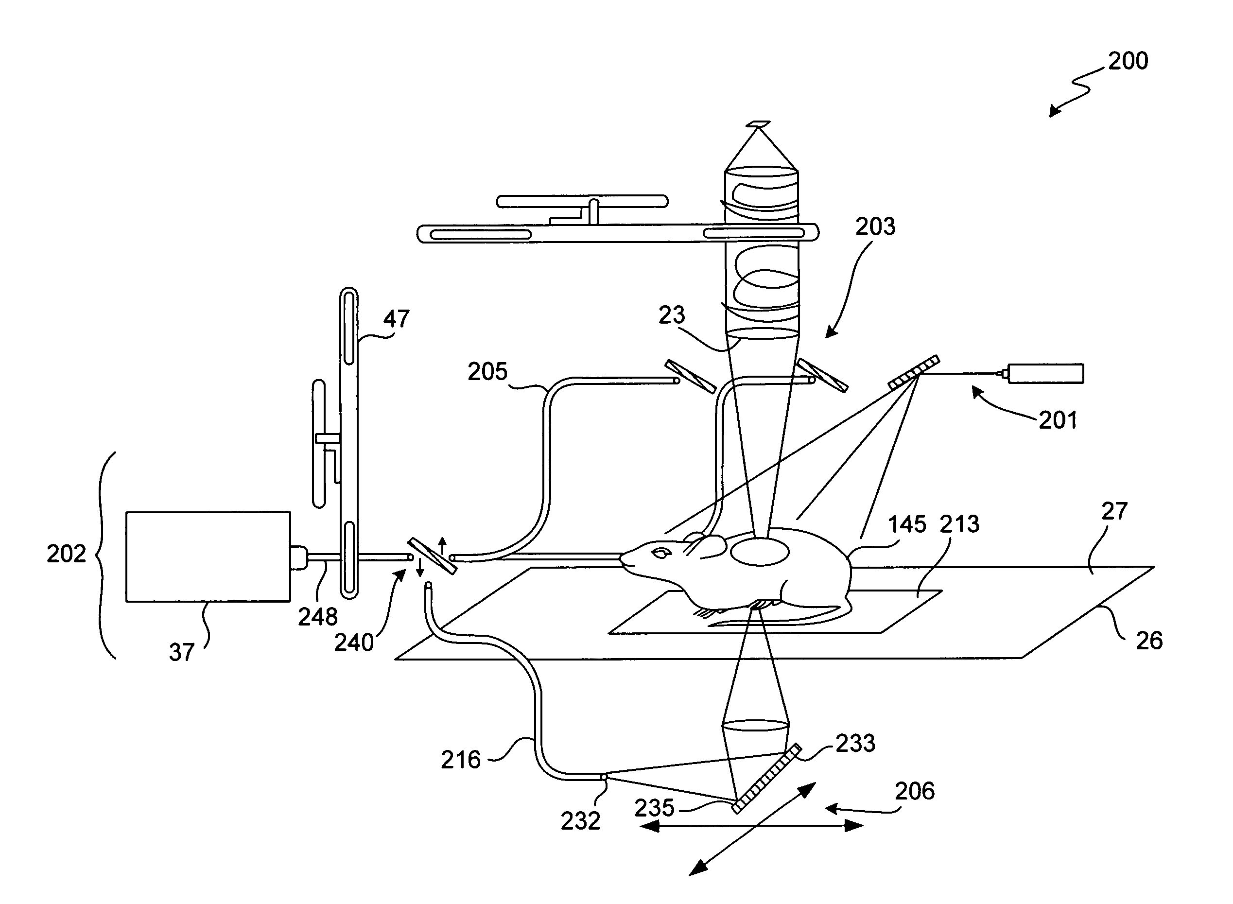
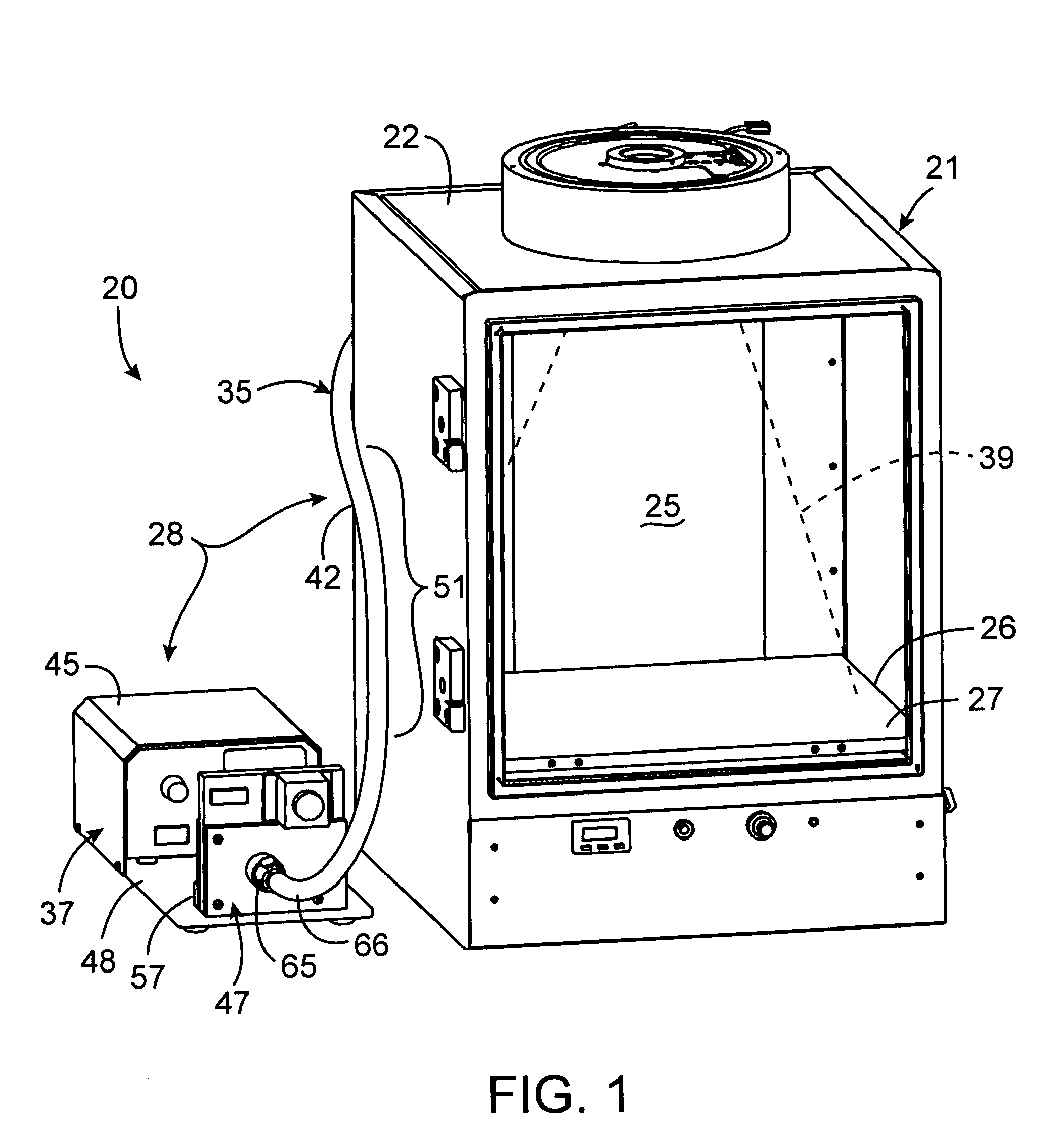
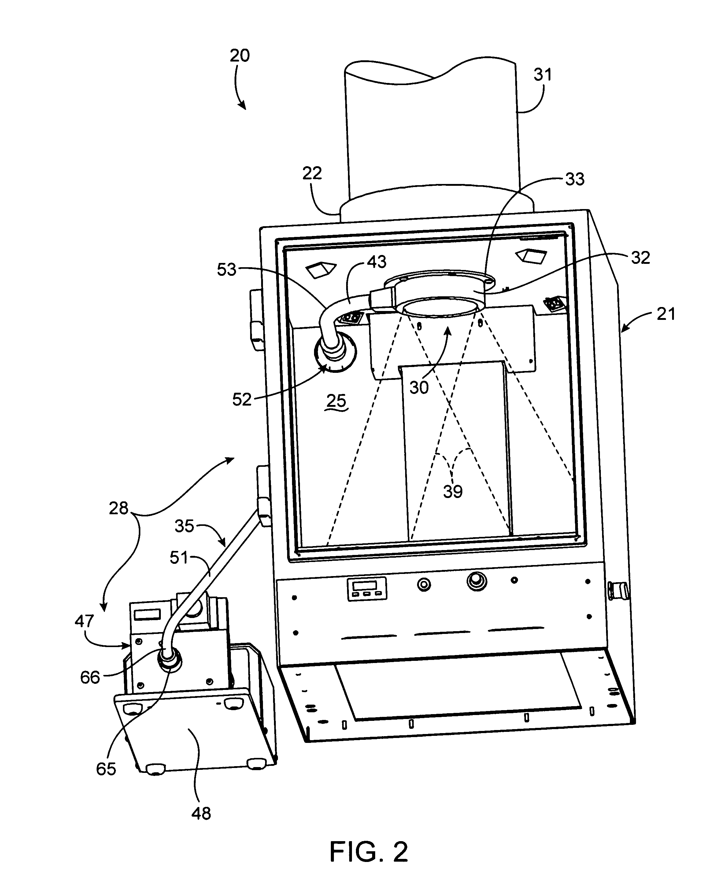
[0048]Referring to FIGS. 10-12, a dual illumination system 200 is provided for use with the same imaging apparatus 21 (generally of FIGS. 1-9) disclosed in the embodiments described in detail below. Similar to those designs, the imaging apparatus at least defines a light-tight imaging compartment 25 with an interior wall 22 having a view port 23 extending therein. This view port 23 enables optical imaging data acquisition of a spec...


PUM

PropertyMeasurementUnit
diameteraaaaaaaaaa
angleaaaaaaaaaa
cone angleaaaaaaaaaa

Abstract

A dual illumination system is disclosed for use with an imaging apparatus. The imaging apparatus defines a light-tight imaging compartment with an interior wall having a view port extending into the imaging compartment. This view port enables data acquisition of a biological specimen contained in the imaging compartment. The dual illumination system includes a first illumination assembly configured to direct structured light onto a first side of the specimen to enable structured light and surface topography measurements thereof. A second illumination assembly then directs light at the specimen wherein diffused fluorescent light emanates from a surface thereof for receipt through the view port to acquire fluorescence data of the specimen. The combination of structured light imaging and fluorescence imaging enables 3D diffuse tomographic reconstructions of fluorescent probe location and concentration.

Description

CROSS-REFERENCE TO RELATED APPLICATION[0001]This application is related to U.S. patent application entitled “BOTTOM FLUORESCENCE ILLUMINATION ASSEMBLY FOR AN IMAGING APPARATUS” by Nilson et al., filed Jun. 17, 2005, U.S. application Ser. No. 11 / 155,078; which in turn is a continuation of a U.S. patent application entitled “BOTTOM FLUORESCENCE ILLUMINATION ASSEMBLY FOR AN IMAGING APPARATUS” by Nilson et al., filed Feb. 21, 2003, U.S. application Ser. No. 10 / 372,763, which in turn is a continuation-in-part of a U.S. patent application entitled “FLUORESCENCE ILLUMINATION ASSEMBLY FOR AN IMAGING APPARATUS” by Nilson et al., filed Jul. 3, 2002, U.S. application Ser. No. 10 / 189,886, now issued as U.S. Pat. No. 6,894,289, which in turn claims priority under 35 U.S.C. 119(e) from U.S. Provisional Patent Application No. 60 / 359,663, entitled same and filed Feb. 22, 2002; all are incorporated herein by reference for all purposes.TECHNICAL FIELD[0002]The present invention relates generally to o...

Claims


Application Information

Patent Timeline
Patent Type & Authority Patents(United States)
IPC IPC(8): G01N21/00G01J3/30G01K9/00
CPCG01N21/6456G01N2021/1787G01N2021/6471G01N2021/6484G01N2201/0227G01N2201/0826
Inventor NILSON, DAVIDRICE, BRADTROY, TAMARA
Owner XENOGEN CORP
Why Eureka
Try Eureka