
System for straining water

a technology of strainer and water, applied in the direction of cleaning with liquids, drawing-off water installations, separation processes, etc., can solve the problems of water system pipes sometimes accumulating, large quantities of water are lost, valves cannot close properly, etc., and achieve the effect of easy assembly and removal

Inactive Publication Date: 2009-01-06
BARRETT II F MADISON
View PDF62 Cites 27 Cited by
  • Summary
  • Abstract
  • Description
  • Claims
  • Application Information

AI Technical Summary

Benefits of technology

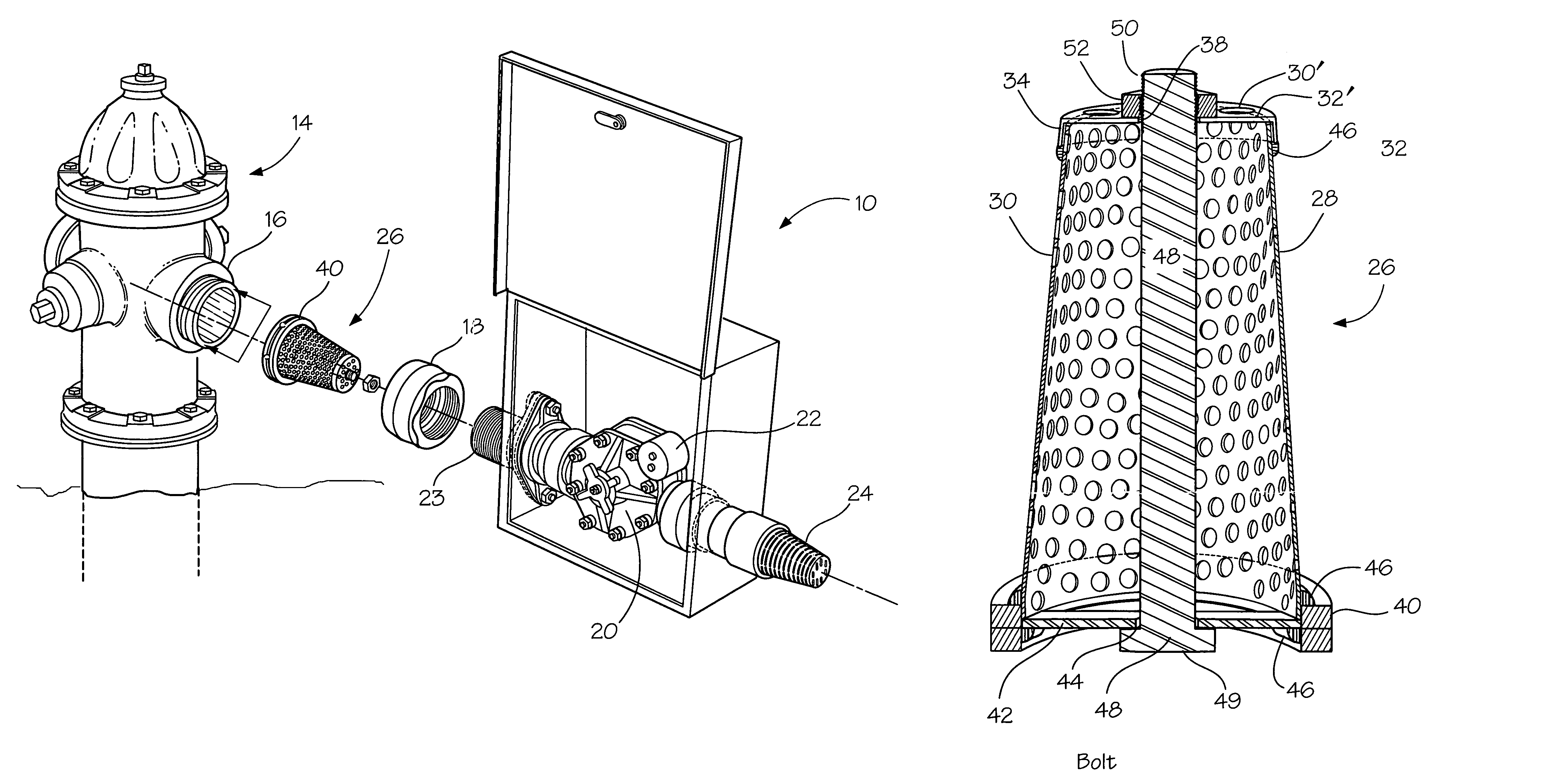
[0006]When the valve is opened by the automatic control, to flush the main line or pipe, debris present in the water as it moves through the strainer toward the valve and the exit end is caught and retained by the strainer. Thus, the debris is prevented from reaching and disabling the operation of the valve.
[0009]The second or larger end of the strainer includes a cross piece which extends across the open end and connects in opposed positions with the flange. The arrangement includes an elongate member which interconnects with the cross piece and the cap to further secure the cap with the first end and the strainer. The elongate member may comprise a bolt and nut which allows for easy assembly and removal. The arrangement provides for adjustable pressure between the cross piece and the cap.
[0015]when the automatic control acts to open the valve, water flows from the main line through the water discharge line through the strainer, through the valve and out a discharge end effectively flushing the system of chemicals and sediment while debris is retained by the strainer and prevented from reaching and blocking the valve in its open position, thus allowing the automatic control to close the valve in a timely fashion.

Problems solved by technology

It has been found that, along with sediment and chemical buildup, water system pipes sometimes accumulate debris or trash which is of a size that can become engaged in the flush valve.
When this occurs, the valve cannot close properly when activated by the automatic control.
The result is large quantities of water are lost and line repairs are necessary to repair the valve for proper closure.

Method used


Image

  • System for straining water
  • System for straining water
  • System for straining water

Examples


Embodiment Construction

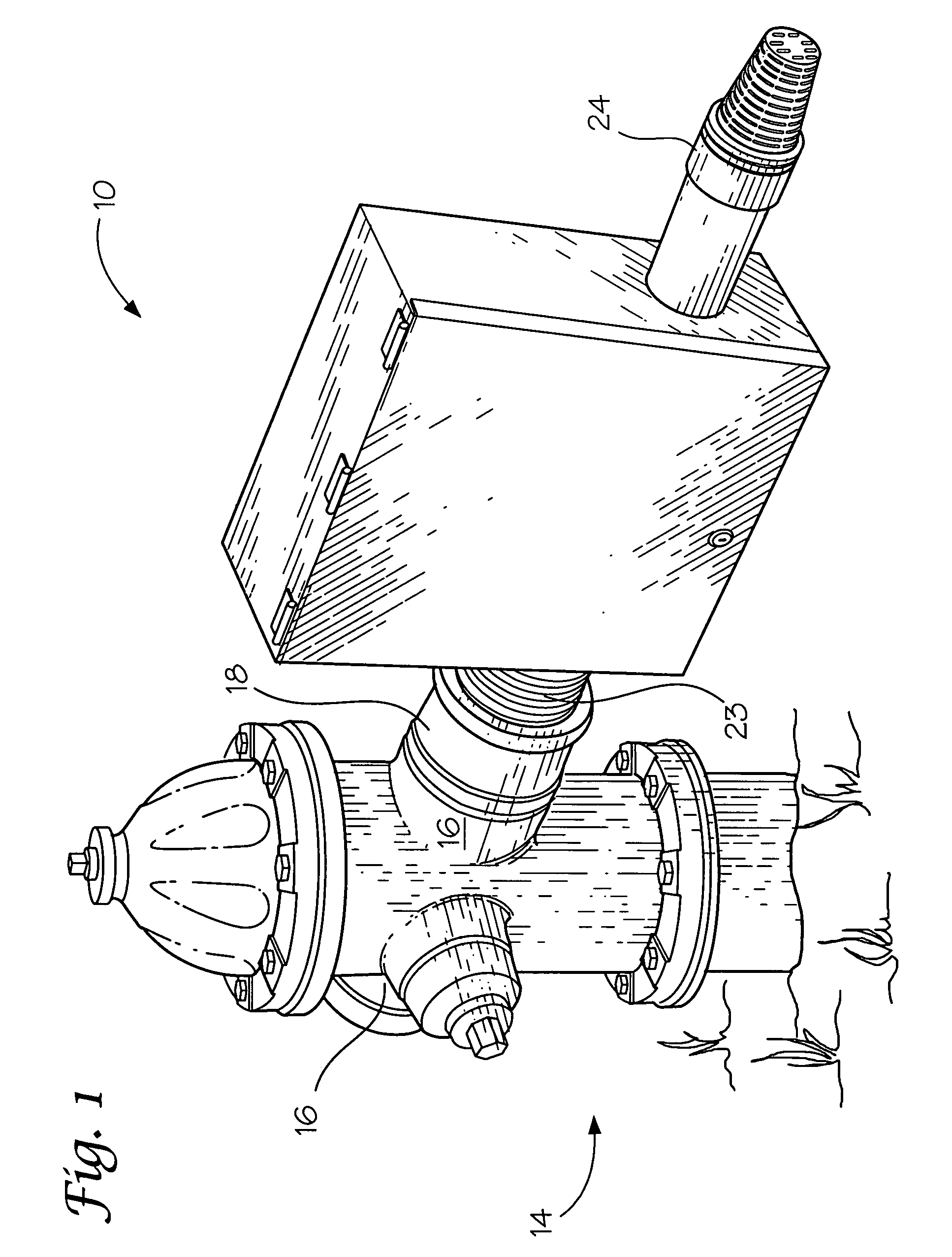
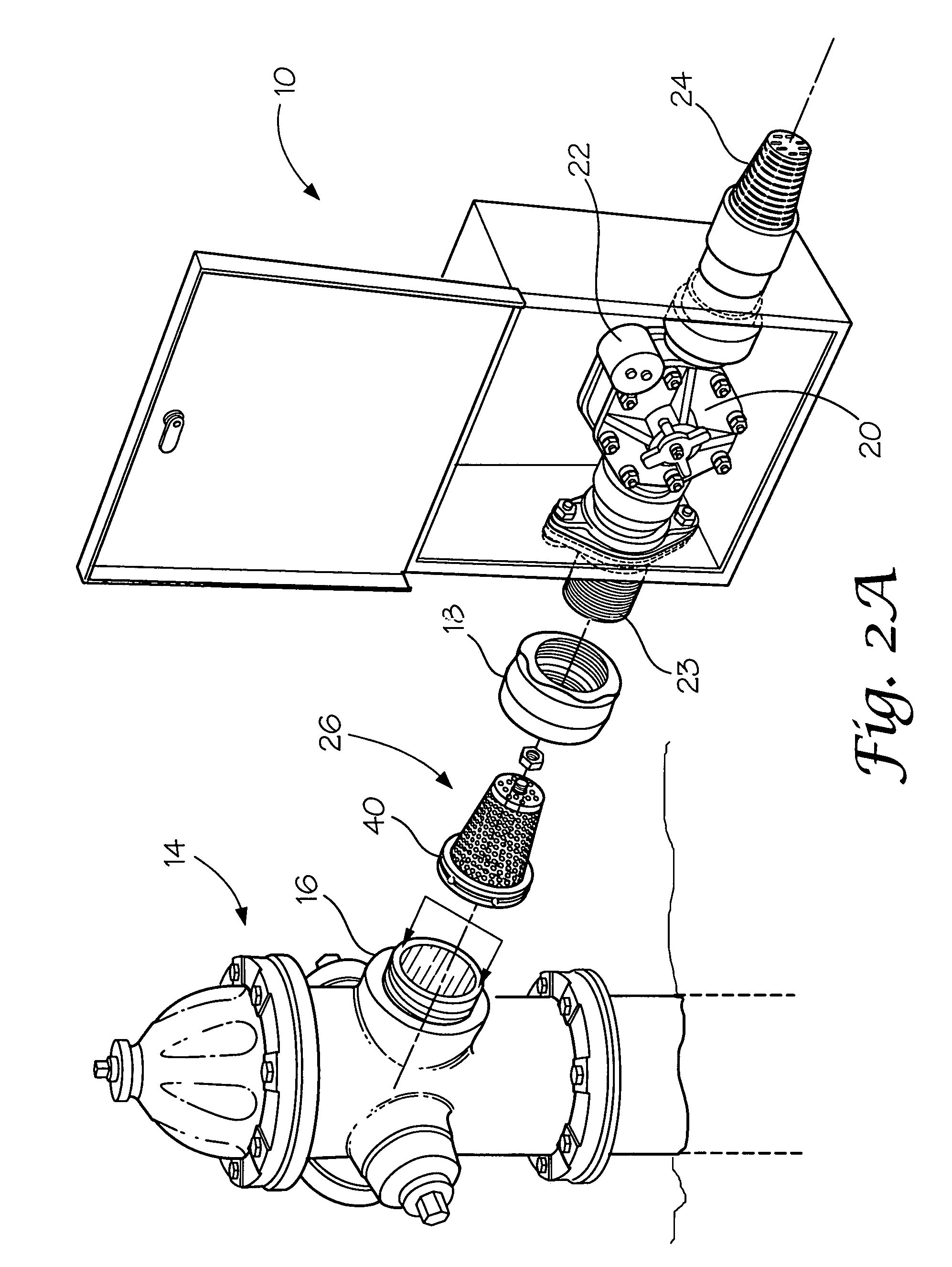
[0023]Turning now to the drawings, FIGS. 1 and 2B show discharge units for use with typical water supply systems.

[0024]As is shown in FIG. 1, a typical discharge system is shown connected to a fire hydrant.

[0025]In FIG. 2B, a known discharge system designed for use in cold climates is shown.

[0026]Typically, the usual water system includes a plurality of distribution or main lines, one of which is shown at 12 in FIG. 2B, which pass through desired areas and are connected by distribution lines to various outlets including residential, commercial, fire hydrants and discharge units. These water systems, over time, begin to accumulate sediment, a chemical buildup, and, in some instances, debris. In order to maintain the water within the system uniformly within pre-set purity standards, it is necessary to flush the system at various intervals, generally one to four times per year.

[0027]Flushing is done usually adjacent line ends or in dead areas where the water is mostly still because unw...


PUM

PropertyMeasurementUnit
Fractionaaaaaaaaaa
Pressureaaaaaaaaaa

Abstract

A water straining system for use in a flushing arrangement for a water delivery system. The flushing arrangement is connected to a main line of the water delivery system and includes a discharge valve controlled by an automatic valve control unit. A filter is positioned in the pipeline of the flushing arrangement between the main line and the automatic valve control. The filter acts to prevent debris in the main line from entering the discharge valve where it could become stuck preventing closure of the discharge valve.

Description

BACKGROUND OF THE INVENTION[0001]The present invention is directed to strainers or filters for use with drinking water systems which are periodically flushed to remove sediment and chemical buildup which accrues over time, particularly in areas of low usage. More specifically, the filters are intended for use with water systems which utilize an automatic control to activate and de-activate the valves used to flush the system in the selected areas.[0002]It has been found that, along with sediment and chemical buildup, water system pipes sometimes accumulate debris or trash which is of a size that can become engaged in the flush valve. When this occurs, the valve cannot close properly when activated by the automatic control. The result is large quantities of water are lost and line repairs are necessary to repair the valve for proper closure.[0003]The strainers or filters of the invention are connected with water pipes of the water system adjacent to and upstream of the flush valve an...

Claims


Application Information

Patent Timeline
IPC IPC(8): B01D25/00B01D35/02B08B9/032E03B9/04
CPCB01D29/35B01D35/02B08B9/027B08B9/0321E03B9/16B01D2201/02Y10T137/0424
Inventor BARRETT, II, F. MADISON
Owner BARRETT II F MADISON
Learn More