
Evaluating method of the residual stress determining method using the continuous indentation method

a continuous indentation and residual stress technology, applied in the direction of simultaneous indication of multiple variables, instruments, mechanical means, etc., can solve the problems of inability to accept the load as being precisely proportional, minute errors due to the difference between ideal values, and inability to accurately determine the residual stress, etc., to minimize errors and minimize errors.

Active Publication Date: 2009-01-06
FRONTICS +1
View PDF8 Cites 13 Cited by
  • Summary
  • Abstract
  • Description
  • Claims
  • Application Information

AI Technical Summary

Benefits of technology

[0035]As is apparent from the above descriptions, the present invention is advantageous in that it provides a method of measuring residual stress, which can minimize error occurring in the residual stress measuring process and agrees with actual models.
[0036]Furthermore, according to the present invention, the conventional complex indentation curve is analyzed such that the dependent part, which has acted as a cause of error in analysis of the indentation curve, is analyzed using a loading curve that is an independent part. In addition, the present invention precisely calculates a contact area by measuring an actual indentation depth which can minimize an error caused by a blunted tip or the pile-up or sink-in of material, and measures residual stress of the material based on the measured contact area.
[0037]In the related art, it has been impossible to estimate the stress-free curve of a weldment or to measure the residual stress of the weldment without using a mechanical / thermal technique. However, in the present invention, the stress-free curve of a weldment can be precisely estimated using an indentation strength ratio (σIT ratio) of a weldment to a residual stress-free base of the material. Thus, the present invention can quantitatively measure the residual stress of a material having a weldment or an anisotropic stress structure.

Problems solved by technology

Particularly, a destructive method of measuring residual stress, in which a specimen is picked up from material to measure residual stress, cannot be used for the measurement of residual stress of buildings or industrial facilities which are actually in use, so that it is necessary to use a nondestructive method to measure the residual stress.
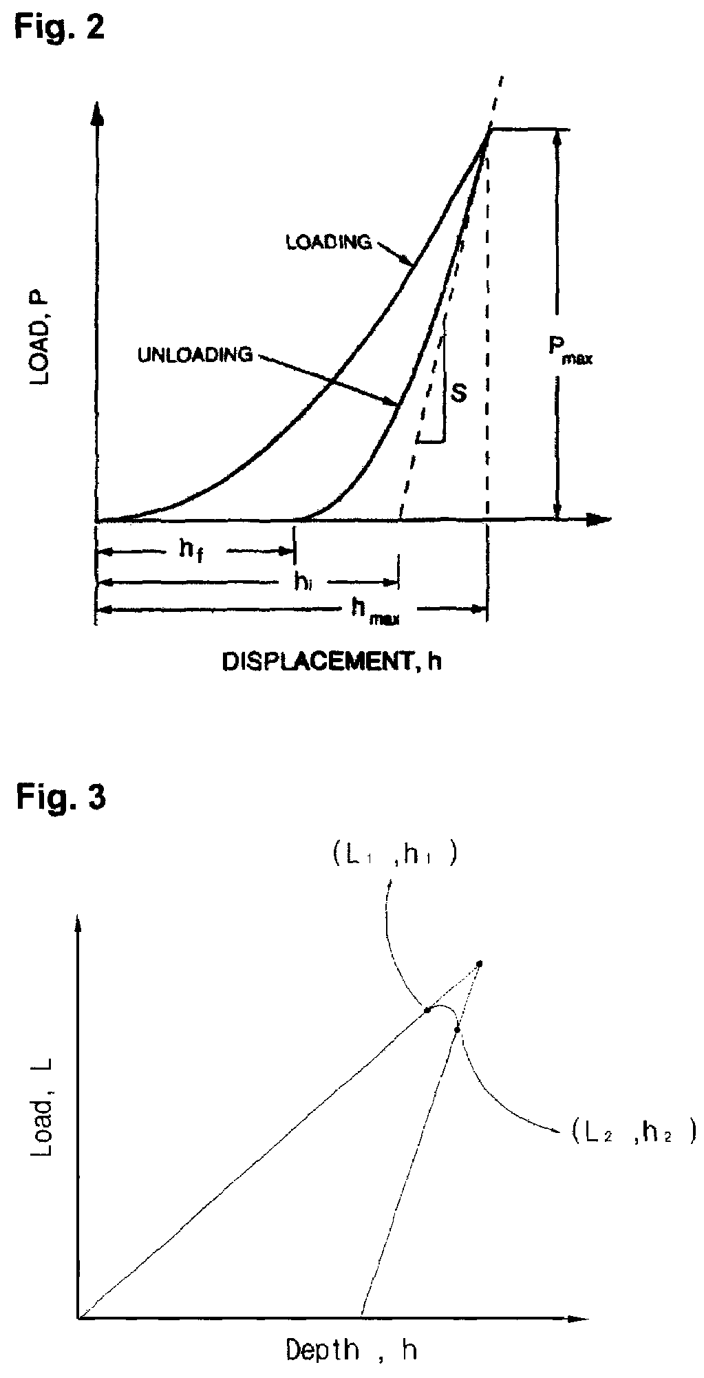
A load applied when Vickers indentation tests, indicating a certain hardness, are executed is proportional to an indentation area, but it is difficult to accept the load as being precisely proportional to the indentation area due to complicated elasticity / plastic strain under the indenter tip.
However, in the conventional method of measuring residual stress, a minute error may occur due to the difference between the ideal value obtained from ideal measurement and the actual value obtained from an actual test.
In other words, when a graph having ideal indentation load-depth curves cannot be obtained, the indentation load may be underestimated or the displacement may be overestimated, so that an error may be generated.
However, a substantial error may occur between an ideal unloading curve and an actual unloading curve, so that it is necessary to eliminate the error.
Furthermore, the conventional method of measuring residual stress cannot account for an error caused by a blunted tip, which has become blunt due to repeated tests, or by pile-up or sink-in of a material, so that measuring results may include an error.
In addition, it is impossible to estimate a stress-free curve of an actual weldment in the stress-free state, so that an error may occur in the measuring results and must be compensated for.
It is impossible to adapt the stress-free curve to a specified region, such as a weldment, which has stresses acting in different directions or having different sizes.
In other words, a stress-free curve cannot be estimated from an actual weldment in a stress-free state, so that, if a stress-free curve is estimated from a material exhibiting an anisotropic stressed state in a weldment, an error may occur in measuring results and must be compensated for.

Method used


Image

  • Evaluating method of the residual stress determining method using the continuous indentation method
  • Evaluating method of the residual stress determining method using the continuous indentation method
  • Evaluating method of the residual stress determining method using the continuous indentation method

Examples


first embodiment

Measurement of Residual Stress of a Material Exclusive of a Weldment

[0103]The method of measuring residual stress of a material exclusive of a weldment is a technique of measuring the residual stress of the material from a normal load difference ΔL, which is conducted through comparison of a reference specimen (stress-free state) and an indentation load-depth curve obtained in a stressed state, and taken from the slope of a curve generated depending on an actual indentation depth hc, contact area Ac, indentation hardness HIT and residual stress. The residual stress measuring method includes steps of: obtaining a stress reference curve in a stress-free state, obtaining a stressed curve in a stressed state, comparing the two curves respectively obtained in the stress-free state and stressed state to each other, and measuring the residual stress of the material using both a load difference ΔL between the two curves obtained through the comparison and a contact area obtained from the lo...

second embodiment

Measurement of Residual Stress for a Weldment

[0152]The biggest problem experienced in the conventional method of measuring residual stress of a weldment resides in that the weldment in a residual stress-free state cannot be measured in the field. Because a material actually used in the field cannot be directly subjected to a mechanical or thermal technique to remove stress, it is not easy to quantitatively measure residual stress of the material. Therefore, to remove stress, a destructive technique must be used. However, the destructive technique of removing stress from a material cannot be adapted to field use, but may only be used in laboratories. Furthermore, to adapt a conventional nondestructive technique to measure residual stress in the field, a physical method is used to approximate a residual stress-free state. However, the conventional nondestructive technique cannot reduce a measurement error caused both by its theoretical background and by data comparison, so that it has...


PUM

PropertyMeasurementUnit
residual stressaaaaaaaaaa
indentation depthaaaaaaaaaa
contact areaaaaaaaaaaa

Abstract

The present invention relates to a method of measuring residual stress and, more particularly, to a residual stress measuring method using a continuous indentation tester. Due to pile-up and sink-in of a material or a blunted tip, a conventional residual stress measuring method cannot compensate for error of a real contact (indentation) depth or directly remove stress through a thermal or mechanical technique in the conventional method of measuring residual stress of a weldment, so that it is very difficult to estimate a stress-free reference curve or to quantitatively measure residual stress. However, the present invention can precisely estimate a stress-free curve of a weldment using an indentation strength ratio (OIT ratio) of a stress-free base metal to the weldment, and compensates for error, occurring in the measurement of a material having a weldment or an anisotropic stress structure, based on the indentation strength ratio, thereby more precisely measuring residual stress. Thus, unlike the conventional method, the present method can minimize error occurring in the residual stress measuring process, and agrees with actual models.

Description

TECHNICAL FIELD[0001]The present invention relates to a method of measuring residual stress and, more particularly, to a method of measuring residual stress using a continuous indentation tester, in which an error caused by pile-up or sink-in of a material or a blunted tip is compensated for precisely measuring residual stress.BACKGROUND ART[0002]In the related art, a method of measuring residual stress present in a specimen while applying a load to the specimen after picking up the specimen from material has been proposed and used. Particularly, a destructive method of measuring residual stress, in which a specimen is picked up from material to measure residual stress, cannot be used for the measurement of residual stress of buildings or industrial facilities which are actually in use, so that it is necessary to use a nondestructive method to measure the residual stress.[0003]Thus, a technique of evaluating residual stress through repeatedly loading and unloading the surface of a m...

Claims


Application Information

Patent Timeline
Patent Type & Authority Patents(United States)
IPC IPC(8): G01N11/00G01N3/00G01N3/42
CPCG01N3/42G01N2203/0076G01N2203/008G01N2203/0082G01N3/48G01N2011/0033G01N2203/0078
Inventor KIM, KWANG HO
Owner FRONTICS
Learn More