
Clean room unit

a technology for cleaning room and unit, applied in the field of cleaning room units, can solve the problems of difficult to leak outside the air containing ingredients of the anti-cancer drug inside the work space, the negative pressure of the clean room, and the increase of the possibility of workers inside the clean room coming, so as to achieve the effect of simplifying the structur

Inactive Publication Date: 2008-12-16
TOSHO INC
View PDF20 Cites 23 Cited by
  • Summary
  • Abstract
  • Description
  • Claims
  • Application Information

AI Technical Summary

Benefits of technology

The present invention is a clean room unit that includes a work room, a clean bench unit, an air conditioning system, and an air conditioning control means. The air conditioning system can perform purification and pressure control of the air inside the work room and the clean bench unit. The clean room unit can be installed inside a building without the need for a separate clean room, reducing the cost of the clean room. The clean room unit allows for the air shower mode for purification and the work mode for preparing medicines. The air conditioning control means can automatically control the air conditioning system based on the air shower mode or the work mode. The clean room unit achieves the advantage of providing a suitable environment for preparing medicines while also reducing the cost of the facility. The clean room unit can also be installed in a pre-room or a clean bench unit, providing flexibility in the installation location. The clean room unit includes an air shower and an automatic mat replacement device for hygienic purposes. The air conditioning system can also include a medicine port for transferring medicines into or out of the work room without opening the entrance / exit of the work room for workers. The clean room unit provides a comfortable and efficient environment for preparing medicines.

Problems solved by technology

On the other hand, when preparing an anti-cancer drug (a powerful medicine), the clean room is negatively pressurized.
However, this increases the possibility of workers inside the clean room coming into contact with air containing the anti-cancer drug ingredient and inhaling the air.
In preparing an anti-cancer drug using the clean bench, if the interior of the work space is negatively pressurized, it becomes difficult for the air containing ingredients of the anti-cancer drug inside the work space to leak outside.
However, the prior art technology has the following problems.
(A) Because a room in the building is itself set aside as a clean room, the clean room becomes unnecessarily large, and in order to maintain the air inside the clean room at a high level of purity, the air purification apparatus is necessarily large.
Also, it takes time to exhaust the air from within the clean room, increasing operating costs.
(B) Furthermore, if a clean bench is separately installed in a clean room, a pre-room for preparing to enter the clean room is separately installed, in which an air shower is installed, making the installation cost to be very high.
However, this is often impossible to realize in consideration of space and cost.
If the clean room is installed independently within a building, although the problems may improve somewhat, the following problems exist.
(a) Because the negatively-pressurized room is installed separate from the positively-pressurized room and the pre-room for performing an air shower is installed separate from the positively-pressurized room and negatively-pressurized room, miniaturization of the clean room has a limit, and the air circulation system may become large.
(b) Furthermore, because the air shower device becomes necessary in the pre-room separate from the air circulation system, the manufacturing cost of the clean room becomes very high.
(c) Because the worker needs to move among rooms of the pre-room, the positively-pressurized room, and the negatively-pressurized room, the workload increases.

Method used


Image

  • Clean room unit
  • Clean room unit
  • Clean room unit

Examples


Embodiment Construction

[0067]Embodiments of the present invention will be described hereafter, based on the drawings. Explanations are given regarding an arrow a in FIG. 1 as being the left direction.

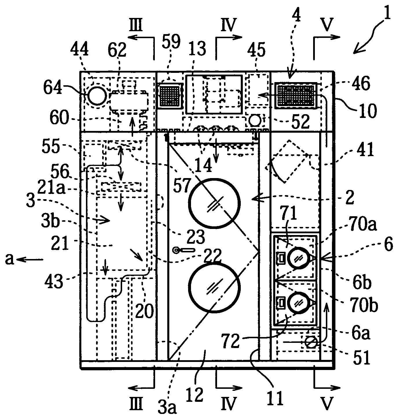
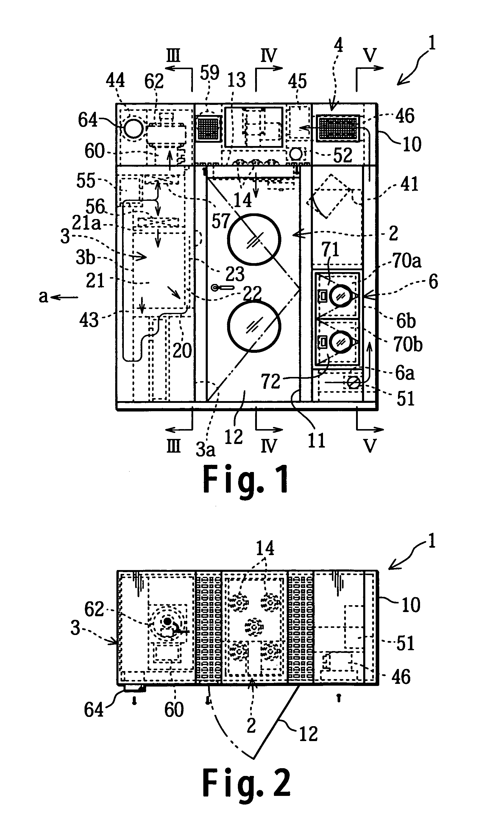
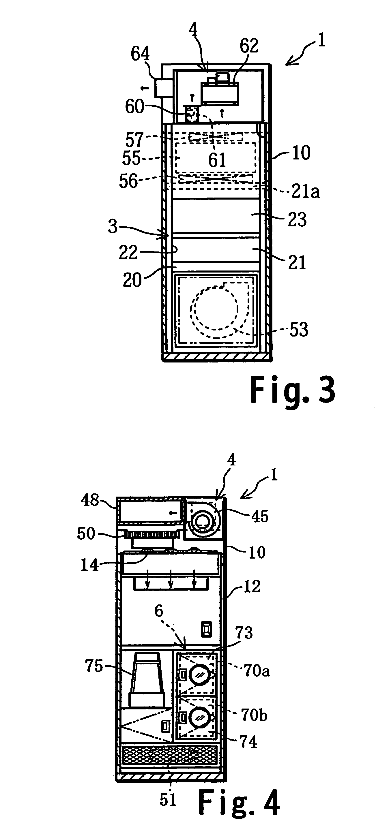
[0068]A clean room unit 1 is installed independently inside a building. As shown in FIG. 1˜FIG. 5, the clean room unit 1 is equipped with a work room 2 isolated from the exterior, a clean bench unit 3 installed so that it has a work opening 22 and the work opening 22 faces to the work room 2, an air conditioning system 4 which can purify and control the air pressure inside the work room 2 and the clean bench unit 3 and generate an air shower inside the work room 2, a control unit 5 (corresponding to an air conditioning control means, see FIG. 7) which controls the air conditioning system 4 and switches the air conditioning system 4 exclusively among the air shower mode which generates an air shower in the work room 2 (see FIG. 9), the ventilation mode which forcibly ventilates the inside of the work room 2 an...


PUM

PropertyMeasurementUnit
heightaaaaaaaaaa
depthaaaaaaaaaa
widthaaaaaaaaaa

Abstract

A clean room unit which is equipped with a work room and a clean bench unit can be independently installed inside a building, can generate an air shower in the work room, and can realize miniaturization and cost reduction. The clean room has a work room, a clean bench unit which has a work opening and has the work opening installed to look onto the work room, an air conditioning system which can perform purification and pressure control of air inside the work room and the clean bench unit and can generate an air shower in the work room, and a control unit. The air conditioning system is controlled by the control unit to switch exclusively between the air shower mode, the ventilation mode, the positively-pressurized work mode, and the negatively-pressurized work mode.

Description

TECHNICAL FIELD[0001]The present invention relates to a clean room unit equipped with a work room and a clean bench isolated from the exterior, installed independently inside a building.BACKGROUND OF THE RELATED ART[0002]Ordinarily, a clean room is installed in medical facilities such as hospitals, in which medicines are prepared. In medical facilities, a room in the building is set aside as a clean room, the air is cleaned by an air conditioner and the pressure adjusted to make it a clean room. When ordinary medicines are prepared in the clean room, the clean room is positively pressurized so that outside air containing bacteria and dust does not enter.[0003]On the other hand, when preparing an anti-cancer drug (a powerful medicine), the clean room is negatively pressurized. Namely, the air inside the clean room where preparation of the anti-cancer drug is performed becomes air containing ingredients of the anti-cancer drug, and the air is prevented from leaking out to outside of t...

Claims


Application Information

Patent Timeline
Patent Type & Authority Patents(United States)
IPC IPC(8): F24F7/06B01L1/04B08B15/02F24F3/16F24F9/00
CPCF24F3/161F24F2009/005F24F2011/0004F24F2011/0005F24F3/167
Inventor OHMURA, SHIROOHMURA, YOSHIHITOHIROBE, HIDEAKIIMURA, TAKEHIKO
Owner TOSHO INC
Learn More