Elevator and traction sheave of an elevator

a technology of traction sheave and elevator, which is applied in the direction of friction gearing, vehicle/pulley ropes, cables, etc., to achieve the effect of preventing wear and damage, ensuring safety, and ensuring safety

Inactive Publication Date: 2008-12-09
KONE CORP
View PDF8 Cites 15 Cited by
  • Summary
  • Abstract
  • Description
  • Claims
  • Application Information

AI Technical Summary

Benefits of technology

[0005]The object of the present invention is to achieve an elevator in which the grip of the traction sheave on the hoisting rope is sufficient even in problem situations where the coating of the traction sheave is lost or damaged. A further object of the invention is to eliminate or avoid the drawbacks of prior-art solutions and to achieve a traction sheave that has a sufficient grip on the hoisting rope even after the coating has been lost and that is also durable and spares the rope against wear and damage. A further object of the invention is to disclose a new type of traction sheave that guarantees a sufficient grip between the traction sheave and the hoisting rope after the coating on the surface of the traction sheave has been lost. It is also an object of the invention to apply the engagement between rope and traction sheave to diverting pulleys that may be comprised in the elevator system.

Problems solved by technology

Thus, as the hoisting ropes bite into the traction sheave material, the elevator will maintain the required grip even in exceptional situations where the coating of the traction sheave is lost or damaged.
The grip between the traction sheave and the hoisting rope in a situation where the coating of the traction sheave has been lost or damaged is a temporary property, which means that the elevator has to be serviced as soon as possible after the coating has been damaged.

Method used


Image

  • Elevator and traction sheave of an elevator
  • Elevator and traction sheave of an elevator
  • Elevator and traction sheave of an elevator

Examples


Embodiment Construction

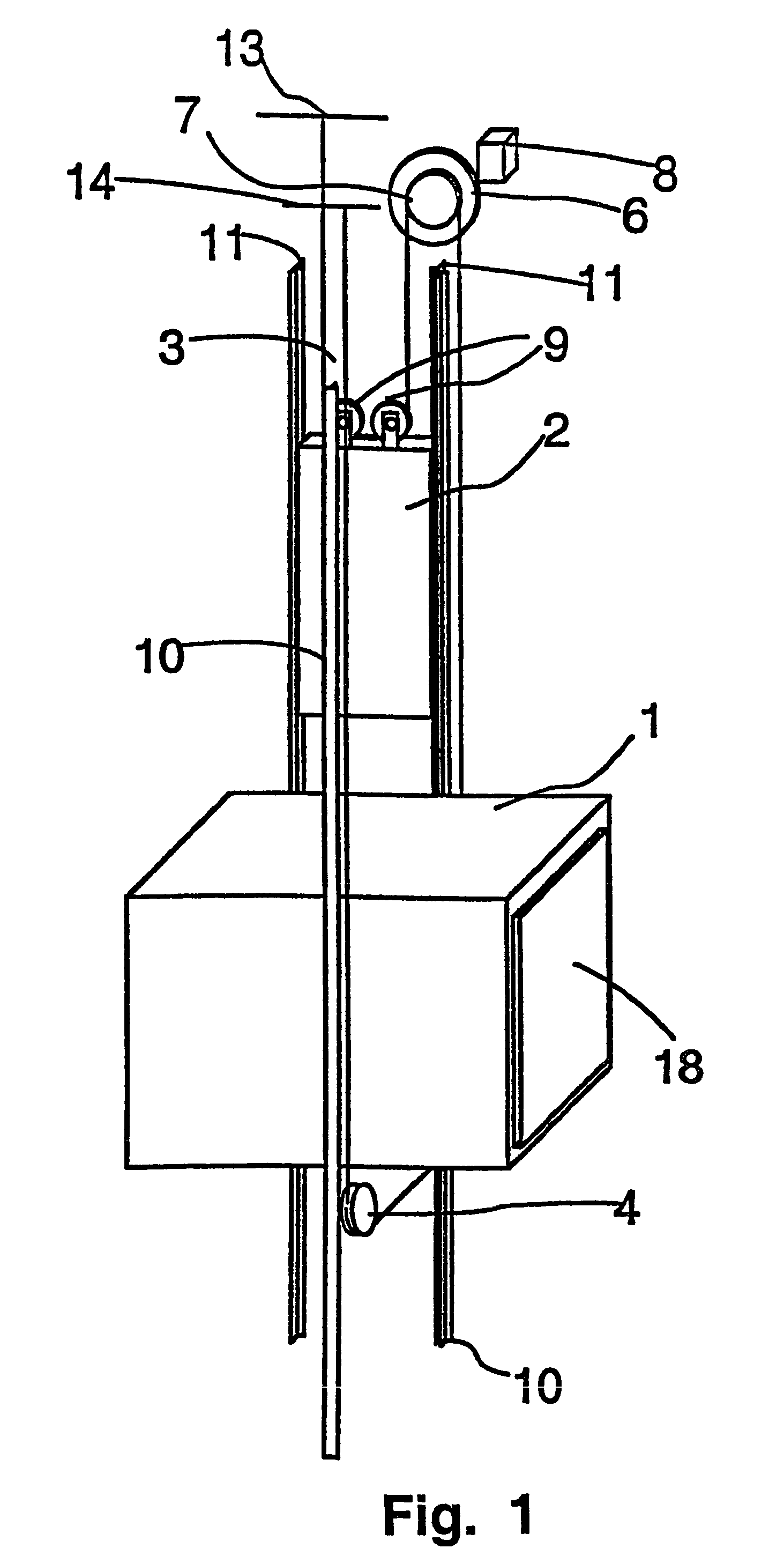
[0024]FIG. 1 is a diagrammatic representation of the structure of an elevator. The elevator is preferably an elevator without machine room, with a drive machine 6 placed in the elevator shaft, although the invention is also applicable for use in elevators having a machine room. The hoisting ropes 3 of the elevator run as follows: One end of the rope set is immovably fixed to an anchorage 13 in the upper part of the shaft above the track of the counterweight 2 moving along counterweight guide rails 11, from where the ropes go downwards to diverting pulleys 9 suspending the counterweight and rotatably connected to the counterweight 2, and from these diverting pulleys 9 the ropes 3 go further upwards to the traction sheave 7 of the drive machine 6, running over the traction sheave along rope grooves provided in it. From the traction sheave 7 the ropes 3 go downwards to the elevator car 1 moving along car guide rails 10, passing under it via diverting pulleys 4 used to suspend the eleva...


PUM


Abstract

An elevator hoisting rope set (3) suspends a counterweight (2) and an elevator car (1). The elevator has one or more rope pulleys provided with rope grooves, one of said rope pulleys being a traction sheave (7) that moves the hoisting ropes (3). At least the traction sheave (7) has against the hoisting rope (3) a coating adhesively attached to it and increasing the coefficient of friction. At least the traction sheave (7) and the hoisting ropes (3) together form a material pair in which the hoisting ropes (3) bite into the traction sheave (7), maintaining a grip sufficient for the operation of the elevator even in an exceptional situation where the coating (102) increasing the coefficient of friction on the surface of the traction sheave (7) is lost.

Description

[0001]This application is a Continuation of copending PCT International Application No. PCT / FI02 / 00153 filed on Feb. 25, 2002, which designated the United States, and on which priority is claimed under 35 U.S.C. § 120, the entire contents of which are hereby incorporated by reference.FIELD OF THE INVENTION[0002]The operation of a conventional traction sheave elevator is based on a solution where steel ropes used as hoisting ropes and at the same time as suspension ropes are moved by means of a metallic, often cast-iron traction sheave driven by a drive machine. The movement of the hoisting ropes produces a movement of the counterweight and elevator car suspended by them. The driving power from the traction sheave to the hoisting ropes, as well as the braking power in braking by means of the traction sheave is transmitted by friction between the traction sheave and the ropes.DESCRIPTION OF THE BACKGROUND ART[0003]The coefficient of friction between the material of the metallic tracti...

Claims


Application Information

Patent Timeline
Patent Type & Authority Patents(United States)
IPC IPC(8): B66B11/08B66D1/00F16H55/36B66B15/04B66B7/06F16G9/00F16H19/02F16H55/38F16H55/50
CPCB66B15/04B66B7/04
Inventor AULANKO, ESKOMUSTALAHTI, JORMA
Owner KONE CORP
Why Eureka
Try Eureka