Radiation detection circuit and apparatus for radiographic examination
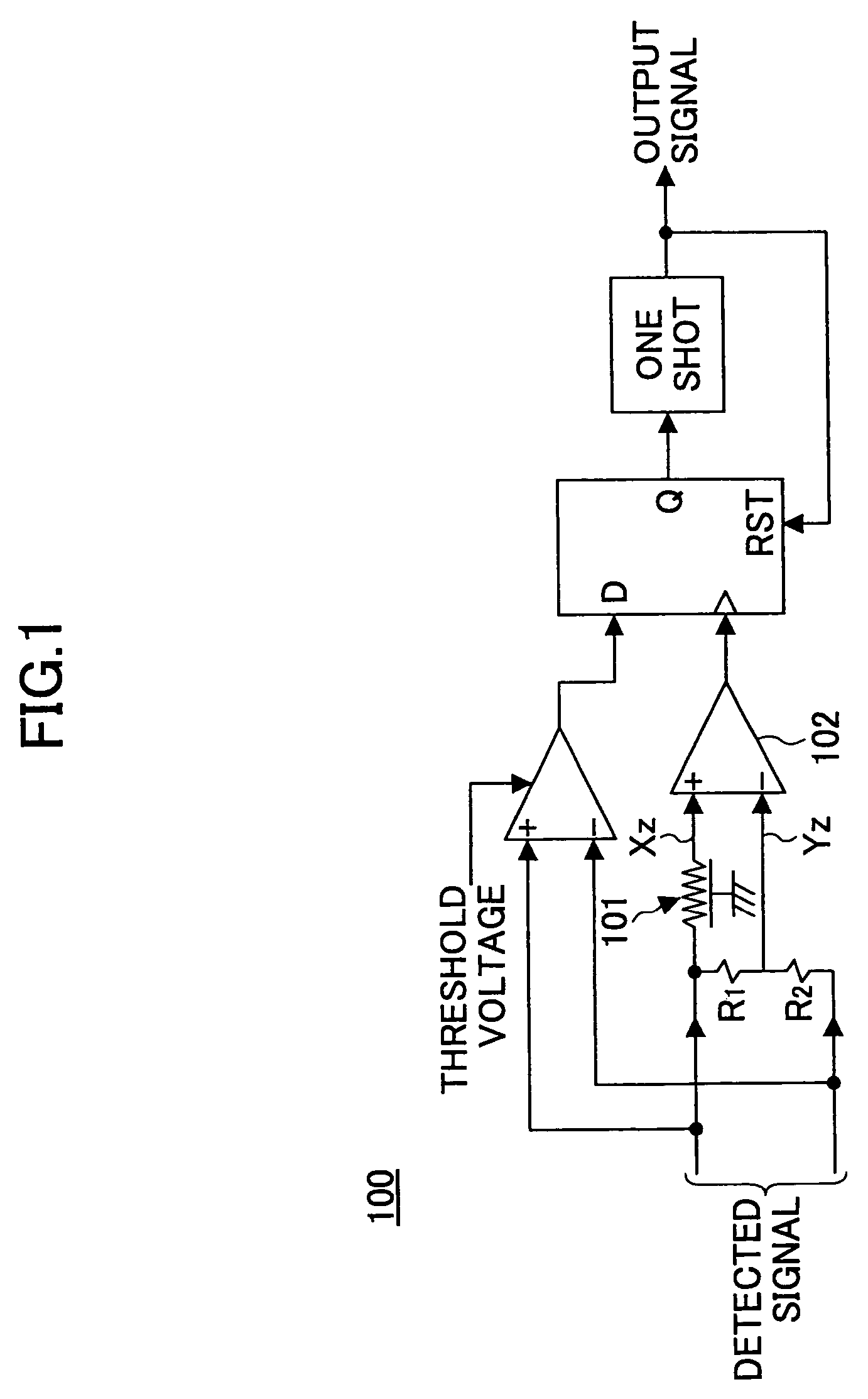
a detection circuit and radiographic examination technology, applied in the direction of instruments, radiation measurement, measurement devices, etc., can solve the problems of increased production costs, complicated configuration of detection circuit b>100/b>, and increased production time of pet apparatus, and achieve the effect of simple circuit configuration
- Summary
- Abstract
- Description
- Claims
- Application Information
AI Technical Summary
Benefits of technology
Problems solved by technology
Method used
Image
Examples
first embodiment
1. First Embodiment
[0032]FIG. 2 is a block diagram illustrating an exemplary configuration of a PET apparatus according to a first embodiment of the present invention. As shown in FIG. 2, a PET apparatus 10 is configured so as to surround an object S and includes detection units 11 for detecting gamma rays each of which detection units 11 includes a detector block 12 and detection circuit 13; an information processing unit 14 for processing detection data and reconstructing image data showing detected positions of positron nuclides in the object S; a display unit 16 for displaying the image data; a control unit 15 for controlling the movement of the object S and the detection units 11; and an input / output unit 18 including a terminal for sending instructions to the information processing unit 14 and the control unit 15 and a printer for outputting image data.
[0033]Prior to examination, a diagnostic agent labeled by a positron nuclide RI is introduced into the object S. The detection...
second embodiment
2. Second Embodiment
[0080]A PET apparatus according to a second embodiment of the present invention is described below. A PET apparatus according to the second embodiment of the present invention has a configuration similar to that of a PET apparatus according to the first embodiment except the configuration of the detection circuit.
[0081]The detector blocks and detectors of a PET apparatus according to the second embodiment have configurations similar to those of the detector blocks and detectors of a PET apparatus according to the first embodiment. Therefore, descriptions of parts having similar configurations are omitted.
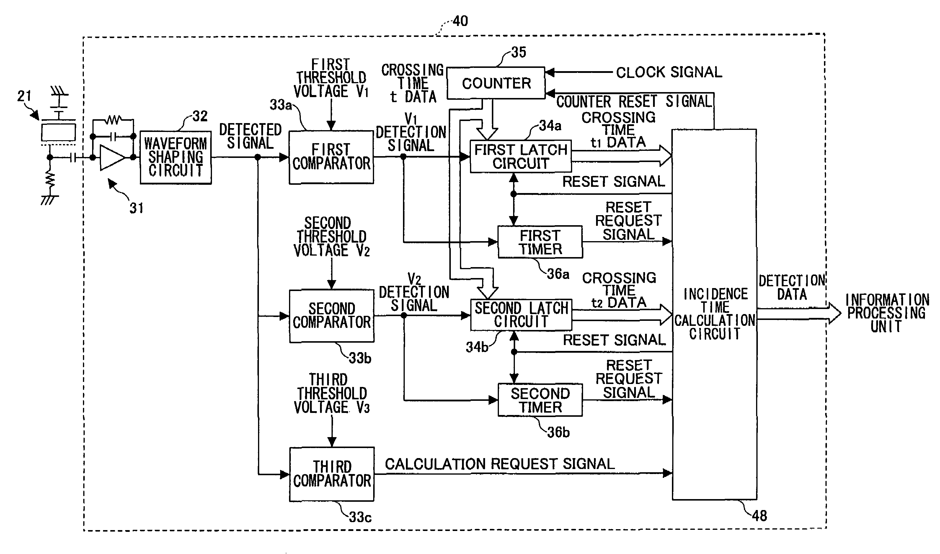
[0082]FIG. 8 is a block diagram illustrating an exemplary detection circuit of a PET apparatus according to the second embodiment of the present invention. In FIG. 8, the same reference numbers are used for parts corresponding to those shown in FIG. 5, and descriptions of those parts are omitted.
[0083]As shown in FIG. 8, the detection circuit 40 includes a preamp...
third embodiment
3. Third Embodiment
[0098]A third embodiment of the present invention is described below. In the third embodiment, some changes are made to the detection circuit 40 according to the second embodiment.
[0099]FIG. 11 is a block diagram illustrating an exemplary detection circuit of a PET apparatus according to a third embodiment of the present invention. In FIG. 11, the same reference numbers are used for parts corresponding to those shown in FIG. 8.
[0100]An exemplary detection circuit of a PET apparatus shown in FIG. 11 is formed on three substrates 41, 42, 43. On the substrate 41, a crystalline application specific integrated circuit (ASIC) is formed. On the substrate 42, a preamplifier circuit 31, a waveform shaping circuit 32, a first comparator 33a, a second comparator 33b, a third comparator 33c, and an encoder 44 are formed. On the substrate 43, a first latch circuit 34a, a second latch circuit 34b, a counter 35, a first timer 36a, a second timer 36b, a decoder 45, and an inciden...
PUM
 Abstract
Description
Claims
Application Information
 - R&D
- Intellectual Property
- Life Sciences
- Materials
- Tech Scout
- Unparalleled Data Quality
- Higher Quality Content
- 60% Fewer Hallucinations
Browse by: Latest US Patents, China's latest patents, Technical Efficacy Thesaurus, Application Domain, Technology Topic, Popular Technical Reports.
© 2025 PatSnap. All rights reserved.Legal|Privacy policy|Modern Slavery Act Transparency Statement|Sitemap|About US| Contact US: help@patsnap.com


