Liquid droplet-jetting head, liquid droplet-jetting apparatus, and liquid droplet-jetting method

a liquid droplet and jetting apparatus technology, applied in the direction of printing, other printing apparatus, etc., to achieve the effect of suppressing the occurrence of resonan

Active Publication Date: 2008-12-02
BROTHER KOGYO KK
View PDF9 Cites 1 Cited by
  • Summary
  • Abstract
  • Description
  • Claims
  • Application Information

AI Technical Summary

Benefits of technology

[0008]An object of the present invention is to provide a liquid droplet-jetting head, a liquid droplet-jetting apparatus, and a liquid droplet-jetting method in which the crosstalk is hardly caused, and the discharge characteristics of the liquid such as the ink are hardly varied.
[0011]In the liquid droplet-jetting head of the present invention, the ratio may be 1.25 to 1.96. In this case, the secondary mode inter-nozzle natural frequency is greater than the jetting frequency. Further, the primary mode inter-nozzle natural frequency is set to be smaller than the jetting frequency. Therefore, the resonance is hardly caused in the secondary or higher order modes, and the primary mode resonance is suppressed as well. Further, the flow passage unit can be realized with ease as compared with a flow passage unit in which the secondary mode frequency is greater than 1.96 times the jetting frequency.
[0028]According to the third aspect of the present invention, it is possible to suppress the occurrence of the resonance in the liquid droplet-jetting head by adjusting the jetting frequency so that the ratio of the secondary mode inter-nozzle natural frequency to the jetting frequency is within the predetermined range.

Problems solved by technology

When the printing is performed by using the head body as described in U.S. Pat. No. 7,048,362 B2, the following problem arises in relation to the ink discharge in some cases due to the vibration of the flow passage unit.

Method used


Image

  • Liquid droplet-jetting head, liquid droplet-jetting apparatus, and liquid droplet-jetting method
  • Liquid droplet-jetting head, liquid droplet-jetting apparatus, and liquid droplet-jetting method
  • Liquid droplet-jetting head, liquid droplet-jetting apparatus, and liquid droplet-jetting method

Examples


Embodiment Construction

[0037]Preferred embodiments of the present invention will be explained below with reference to the drawings.

Outline of Printer

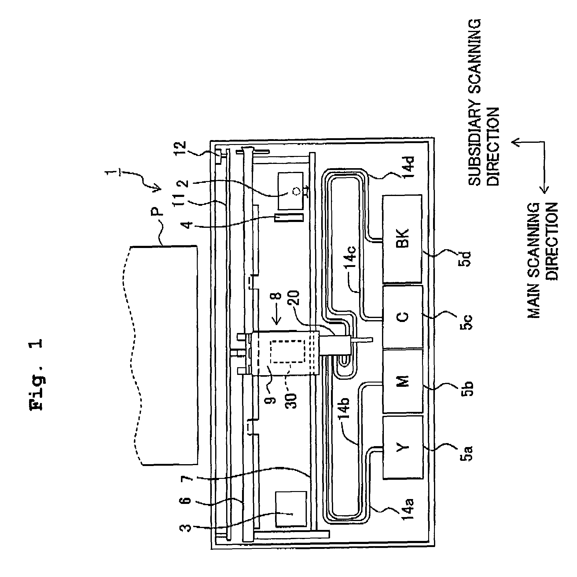
[0038]FIG. 1 shows a schematic top view illustrating an ink-jet printer 1 in which an ink-jet head body according to an exemplary embodiment of the present invention is provided. The ink-jet printer 1 will be referred to as “printer 1” below in an abbreviated manner.

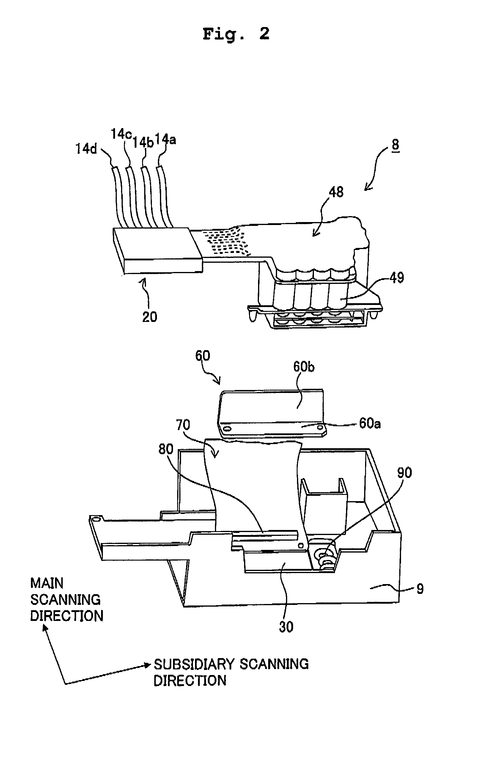
[0039]Two guide shafts 6, 7 are provided in the printer 1. A head unit 8, which serves as a carriage, is provided on the guide shafts 6, 7 so that the head unit 8 is capable of reciprocating in the main scanning direction. The head unit 8 has a head holder 9 which is formed of a synthetic resin material. An ink-jet head 30, which performs the printing operation by discharging the inks onto the printing paper P transported to the position under or below the head unit 8, is held by the head holder 9.

[0040]A carriage motor 12 is provided on the printer 1. An endless belt 11, which is rotated in accor...


PUM


Abstract

In an ink-jet head having a plurality of nozzles for discharging liquid droplets, vibration is generated in a direction connecting two nozzles, of the nozzles, by the discharge operation performed at least one of the nozzles. In particular, when the printing frequency is in the vicinity of the secondary mode frequency (for example, 27.5 kHz) of the proper vibration of the ink-jet head, the crosstalk easily arises. The crosstalk is hardly caused when the ratio of the secondary mode frequency of the ink-jet head to the printing frequency is any one of a value of not more than 0.85, a value in a range of 1.25 to 1.96, and a value of not less than 4.59.

Description

CROSS REFERENCE TO RELATED APPLICATION[0001]The present invention claims priority from Japanese Patent Application No. 2005-302834, filed on Oct. 18, 2005, the disclosure of which is incorporated herein by reference in its entirety.BACKGROUND OF THE INVENTION[0002]1. Field of the Invention[0003]The present invention relates to a liquid droplet-jetting head, a liquid droplet-jetting apparatus, and a liquid droplet-jetting method for discharging or jetting a liquid onto an object.[0004]2. Description of the Related Art[0005]The liquid droplet-jetting head, which is used, for example, as an ink-jet head body of a printer, includes a liquid droplet-jetting head as described in U.S. Pat. No. 7,048,362 B2 (corresponding to Japanese Patent Application Laid-open No. 2004-160915). The head body described in U.S. Pat. No. 7,048,362 B2 has a plurality of nozzles for discharging or jetting the ink. The nozzles are formed on a lower surface of a flow passage unit (channel unit) which is installe...

Claims


Application Information

Patent Timeline
Patent Type & Authority Patents(United States)
IPC IPC(8): B41J2/045
CPCB41J2/04525B41J2/04581B41J2/14209B41J2/17509B41J2/17513B41J2/1752B41J29/377B41J2002/14217B41J2002/14225B41J2002/14459B41J2002/14491
Inventor ISHIKAWA, HIROYUKI
Owner BROTHER KOGYO KK
Why Eureka
Try Eureka