
Circuit and method of compensating for signal delay in a cable

a technology of compensating circuit and delay, applied in the field of compensating circuit and method, can solve the problems of difficult to compensate for asynchronous signal transmission, operation error, and degradation of image quality, and achieve the effect of mitigating asynchronous signal transmission

Active Publication Date: 2008-11-25
ATEN INT CO
View PDF4 Cites 6 Cited by
  • Summary
  • Abstract
  • Description
  • Claims
  • Application Information

AI Technical Summary

Benefits of technology

[0006]It is an aspect of the present invention to provide a compensation circuit for a cable which mitigates asynchronous signal transmission caused by different lengths of its enclosed transmission lines.
[0008]It is another aspect of the present invention to provide a method of compensating for delay in a cable, which can automatically compensate the asynchronous signal transmission between different transmission lines.
[0010]It is still another aspect of the present invention to provide a computer switching system, which can achieve the RGB balance of color signals.

Problems solved by technology

When the length of the cable is too long, the video signals are considerably attenuated, thus degrading the quality of images and causing an operation error because of the unclear display.
It is difficult to compensate for asynchronous signal transmission due to different lengths, especially for the cables of various lengths and types implemented in a computer system.

Method used


Image

  • Circuit and method of compensating for signal delay in a cable
  • Circuit and method of compensating for signal delay in a cable
  • Circuit and method of compensating for signal delay in a cable

Examples


Embodiment Construction

[0022]Reference will now be made in detail to the present preferred embodiments of the invention, examples of which are illustrated in the accompanying drawings. Wherever possible, the same reference numbers are used in the drawings and the description to refer to the same or like parts.

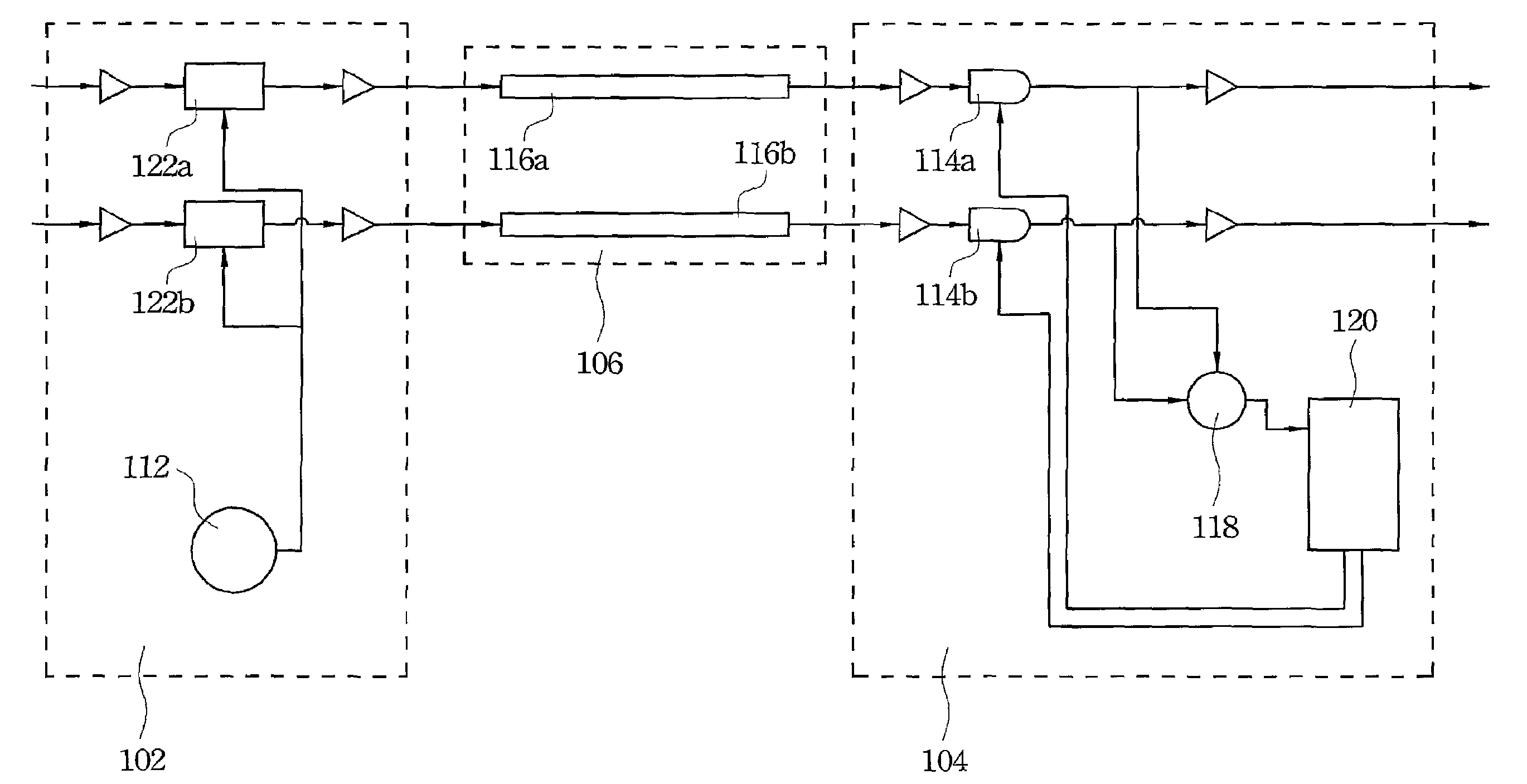
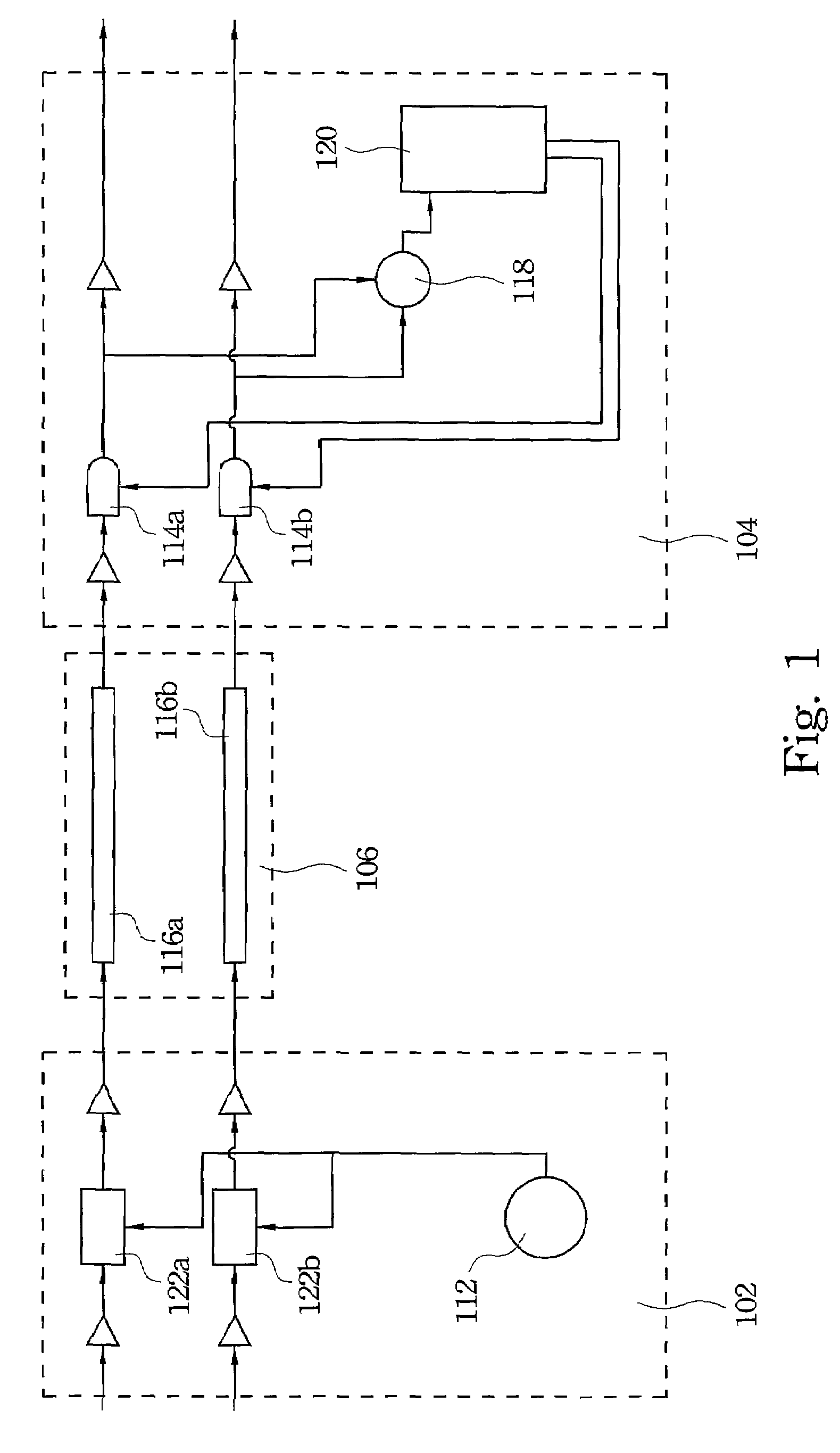
[0023]FIG. 1 is a compensation circuit according to one embodiment of the present invention. A cable 106, which is capable of connection between a first device 102 and a second device 104, has a first transmission line 116a and a second transmission line 116b provided for transmitting analog signals, respectively. These transmission lines 116a and 116b are generally twisted within the cable 106, thus particularly having different lengths that may cause asynchronous signal transmission.

[0024]The compensation circuit has an oscillator 112, a first variable delay line 114a, a second variable delay line 114b, a phase detector 118 and a controller is 120. The oscillator 112 generates an oscillation signal...


PUM

PropertyMeasurementUnit
frequencyaaaaaaaaaa
frequencyaaaaaaaaaa
phase detectoraaaaaaaaaa

Abstract

The compensation circuit comprises an oscillator, a first variable delay line, a second variable delay line, a phase detector and a controller. The oscillator generates an oscillation signal to input into a first transmission line and a second transmission line. The first variable delay line receives the oscillation signal transmitted through the first transmission line. The second variable delay line receives the oscillation signal transmitted through the second transmission line. The phase detector compares the phases of the two oscillation signals from the variable delay lines to generate a phase difference signal. The controller adjusts the variable delay lines to compensate for asynchronous signal transmission of the transmission lines according to the phase difference signal.

Description

BACKGROUND[0001]1. Field of Invention[0002]The present invention relates to a compensation circuit and method. More particularly, the present invention relates to a circuit and method of compensating for delay in a cable.[0003]2. Description of Related Art[0004]With the rapid development of information technology, computers and their peripherals have become very popular. Users can control computers by mice and keyboards, and monitor the states of their computers through monitors. In a computer system, video signals are transmitted to a monitor from a video adapter via a cable. When the length of the cable is too long, the video signals are considerably attenuated, thus degrading the quality of images and causing an operation error because of the unclear display.[0005]Moreover, the cable generally has three transmission lines provided for signals of three different colors, respectively. The transmission lines may have different lengths, causing the signals transmitted thereby asynchr...

Claims


Application Information

Patent Timeline
Patent Type & Authority Patents(United States)
IPC IPC(8): H02J3/22H01B11/12H04B3/46
CPCH03K5/135H03K5/145H04L25/03885H04L25/08H03H7/325H03K2005/00071
Inventor SHEN, FU-CHIN
Owner ATEN INT CO
Learn More