
Rail system

a rail system and rail technology, applied in the direction of electrical equipment, packaging, coupling device connections, etc., can solve the problems of difficult to achieve privacy for face-to-face or telephone conversations, meetings or other commercial interior activities, and commercial interiors that involve relatively “stationary” furniture, and do not necessarily lend themselves to rapid reconfiguration

Inactive Publication Date: 2008-11-25
HERMAN MILLER INC
View PDF5 Cites 78 Cited by
  • Summary
  • Abstract
  • Description
  • Claims
  • Application Information

AI Technical Summary

Benefits of technology

"The invention is an overhead infrastructure for commercial interiors that allows for easy reconfiguration and control of power and communication accessories. It consists of a rail system that allows for the connection of various functional accessories and communication devices. The system is designed to be easily installed and maintained, with minimal disruption to the interior design. It also allows for quick reconfiguration and control of environmental conditions, such as lighting and temperature, by the occupants of the interior. Overall, the invention provides a more flexible and efficient solution for upgrading and improving commercial interiors."

Problems solved by technology

With the exception of executive offices, privacy for face-to-face or telephone conversations, meetings or other commercial interior activities was difficult to achieve.
Although building owners and tenants began to concern themselves with the foregoing, commercial interiors still typically involved very heavy and relatively “stationary” furniture.
Although modular systems present an advance in the architectural arts, there are still a number of considerations which are not met by these systems.
For example, although these systems are sometimes characterized as “modular,” they do not necessarily lend themselves to rapid reconfiguration.
For example, partitions (although described as “movable”) often require a significant amount of work to reconfigure.
Further, although these systems employ interchangeability of hanging and supporting components, assembly and disassembly of these systems (even beyond the movable partitions) require a substantial amount of work, and usually involve maintenance personnel with particular expertise.
Still further, although these systems may involve lighting controllable by the workspace user, most environmental functions remain centrally controlled, often at a location substantially remote from the commercial interior being controlled.
In the past, problems associated with difficulty in reconfiguration of commercial interior, and lack of in situ control of a location's environmental conditions may not have been of primary concern.
However, today's business climate often involves relatively “fast changing” commercial interior needs.
However, when these structures, which can be characterized as somewhat “permanent” in most buildings (as described in previous paragraphs herein), are designed, the actual occupants may not move into the building for several years.
Needless to say, in situations where the building will not be commissioned for several years after the design phase, the infrastructure of the building may not be appropriately laid out for the actual occupants.
However, as previously described herein, most commercial interiors permit little reconfiguration after completion of the initial design.
Reconfiguring a structure for the needs of a particular tenant can be extremely expensive and time consuming.
However, many business organizations today experience relatively rapid changes in growth, both positively and negatively.
When these changes occur, again it may be difficult to appropriately modify the commercial interior so as to permit the occupant to expand beyond its original commercial interior or, alternatively, be reduced in size such that unused space can then be occupied by another tenant.
Other problems also exist with respect to the layout and organization of today's commercial interiors.
To modify these control relationships in most commercial interiors requires significant efforts.
An inverted T-runner is engaged with the spline, in a manner so that when the ceiling system is exposed to heat, the inverted T-runner continues to hold the ceiling panels even, although the spline loses structural integrity and may disengage from the trim.

Method used


Image

  • Rail system
  • Rail system
  • Rail system

Examples


Embodiment Construction

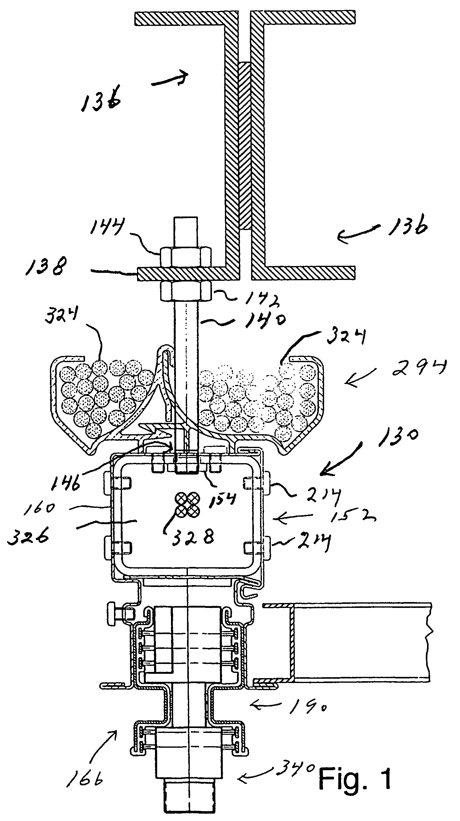
[0062]The principles of the invention are disclosed, by way of example, within a rail system 100 illustrated in FIGS. 1-32. A general layout of the rail system 100 as used within a series of reconfigurable commercial interiors s is illustrated in FIG. 3. Structural layouts of the rail system employing certain of its principal components are also illustrated in FIGS. 14, 17, 21A, 26, 27, 28, 29 and 29A. The rail system 100 comprises an overhead structure providing significant advantages in environmental workspaces. As examples, the rail system 100 in accordance with the invention facilitates access to locations where a commercial interior designer may wish to locate various functional elements, including electrical power receptacles and the like. In addition, the rail system 100 facilitates flexibility and reconfiguration in the location of various functional elements which may be supported and mounted in a releasable and reconfigurable manner with the rail system. Still further, the...


PUM


Abstract

A rail system (100) is disclosed which may be employed within a commercial interior (102). The rail system (100) comprises a series of primary-tracks (130) in a spaced apart configuration. The rail system (100) also comprises a series of cross rails (132) releasably interconnectable to the primary tracks (130). The rail system (100) permits electrical and mechanical interconnections and reconfiguration of electrical and mechanical interconnections, for various functional accessories and communications.

Description

CROSS-REFERENCE TO RELATED APPLICATIONS[0001]This international application is based upon and claims priority of U.S. Provisional Patent Application Ser. No. 60 / 408,149 filed Sep. 4, 2002.STATEMENT REGARDING FEDERALLY SPONSORED RESEARCH OR DEVELOPMENT[0002]Not applicable.REFERENCE TO A MICROFISHE APPENDIX[0003]Not applicable.BACKGROUND OF THE INVENTION[0004]1. Field of the Invention[0005]The invention relates to an overhead infrastructure for commercial interiors (i.e. commercial, industrial, residential and office environments) requiring power and cable access and, more particularly, to a rail system which permits electrical and mechanical interconnections (and reconfiguration of electrical and mechanical interconnections) of various functional accessories, and communications (including reconfiguration of controlled / controlling relationships) among the accessories.[0006]2. Background Art[0007]Building infrastructure continue to evolve in today's commercial, industrial and office en...

Claims


Application Information

Patent Timeline
Patent Type & Authority Patents(United States)
IPC IPC(8): H01R25/00B65G
CPCH01R25/14H01R25/142
Inventor INSALACO, ROBERT W.HOWE, RUSSELLONG, JAMES B.MILLIS, W. DANIEL
Owner HERMAN MILLER INC
Learn More