
Methods and systems for modeling material behavior

a material behavior and modeling system technology, applied in the direction of force/torque/work measurement apparatus, force sensors, instruments, etc., can solve the problems of relative inflexibility, limited learning capacity of given constitutive model, and inability to capture the complex behavior of geologic materials

Inactive Publication Date: 2008-11-04
THE BOARD OF TRUSTEES OF THE UNIV OF ILLINOIS
View PDF3 Cites 18 Cited by
  • Summary
  • Abstract
  • Description
  • Claims
  • Application Information

AI Technical Summary

Benefits of technology

This approach allows for more accurate and flexible modeling of soil behavior, reducing the need for extensive testing and enabling better prediction of soil response under various conditions, leading to improved design and construction practices.

Problems solved by technology

These models are useful to establish a general framework for understanding material behavior but do not capture the complex behavior of geologic materials including non-linearity, hardening and softening, anisotropy, and strain rate dependence.
A disadvantage associated with these models is there relative inflexibility.
A given constitutive model has very limited learning capacity through adjustment of model properties.
This general process as currently known, however, leaves many problems unresolved.
The data obtained from current laboratory and / or field-testing procedures and apparatuses, for example, are often not sufficient as a basis for comprehensive modeling.
These devices are generally unable to obtain some data important for soil modeling, such as the soil friction angle.
Although this technique can be used to interpret strains, it is unable to develop the stress-strain relationship unless data such as the soil friction angle is assumed.
Additional problems are presented in the extent of testing required using presently known apparatuses and methods.
Soil behavior is highly anisotropic and is difficult to fully characterize using a single test device.
Historically, a large number of laboratory tests have been required using a range of test devices to obtain even a limited characterization of the soil properties.
In the prior art, however, these model adjustments have only been made on an ad-hoc basis, with the result that they may be inconsistent and not accurately applied.
Also, many models developed using laboratory and / or field-testing do not have the flexibility to be readily adjusted.
These and other problems remain unresolved in the art.

Method used


Image

  • Methods and systems for modeling material behavior
  • Methods and systems for modeling material behavior
  • Methods and systems for modeling material behavior

Examples


Embodiment Construction

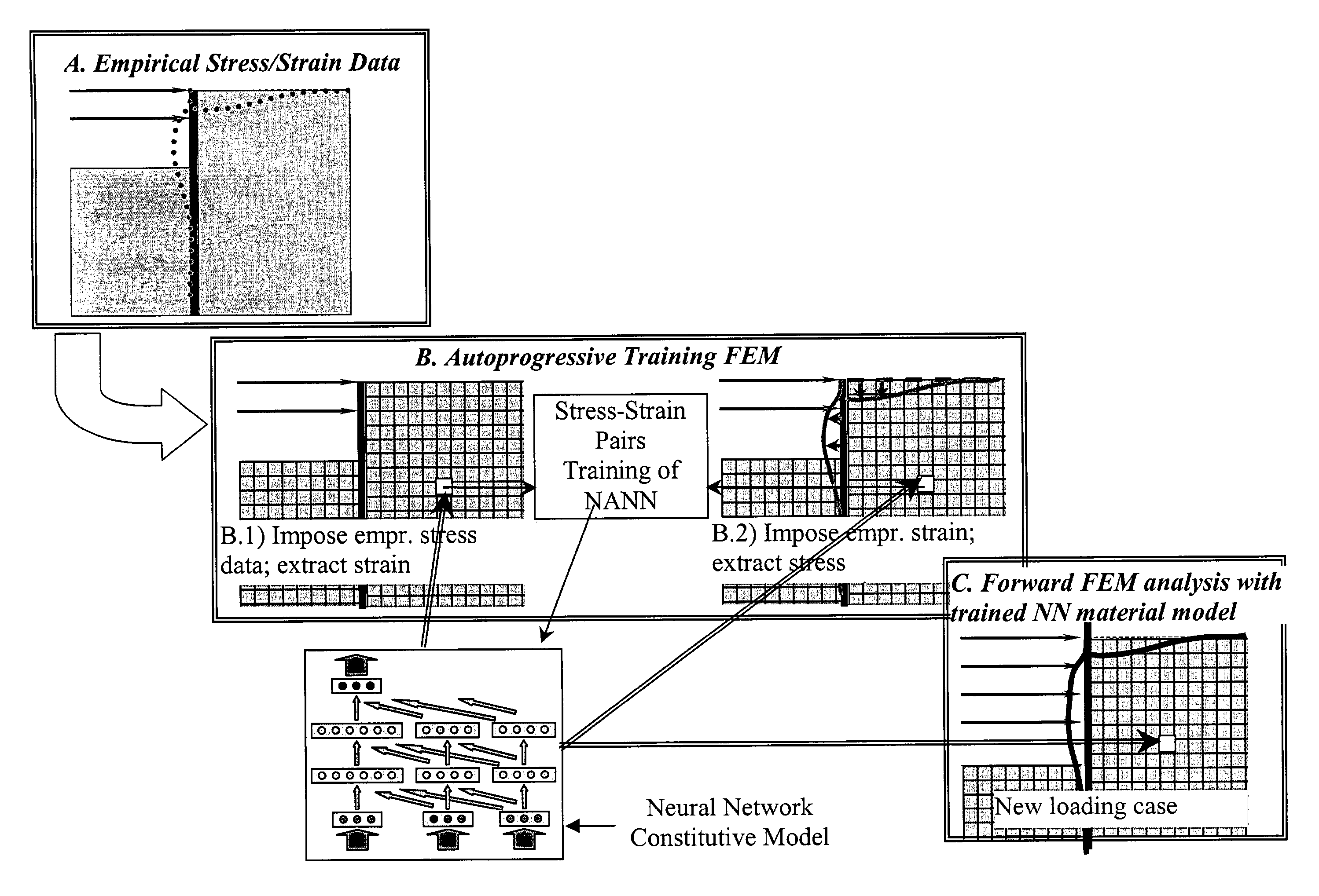
[0031]The present invention is directed to systems and methods for modeling material behavior. A preferred embodiment of the invention is directed to method for modeling material behavior that includes using a testing device to induce a non-uniform state of stress and strain in a material sample and to measure data with the testing device. The data is then used to train a self-organizing computational model to learn non-uniform stress and strain behavior of the material. Other aspects of the present invention are directed to devices for obtaining the empirical stress and strain data. The devices include field testing devices and methods, laboratory testing devices and methods, and field observation methods.

[0032]It will be appreciated that methods and devices of the invention lend themselves well to practice in the form of computer program products. For example, a method or device of the invention may include a computer program product that causes a processor-based device to carry o...


PUM

PropertyMeasurementUnit
distanceaaaaaaaaaa
stressaaaaaaaaaa
stiffnessaaaaaaaaaa

Abstract

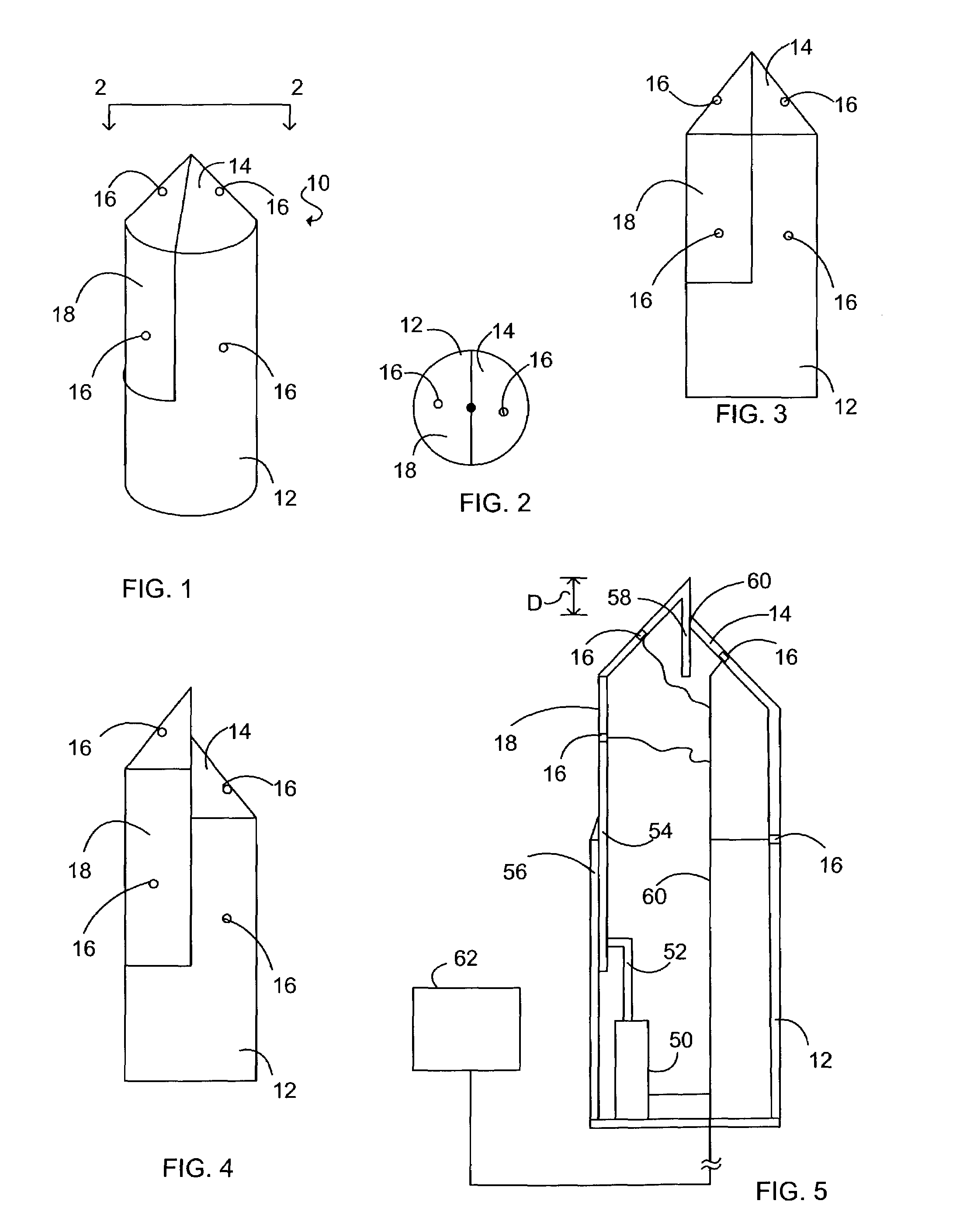
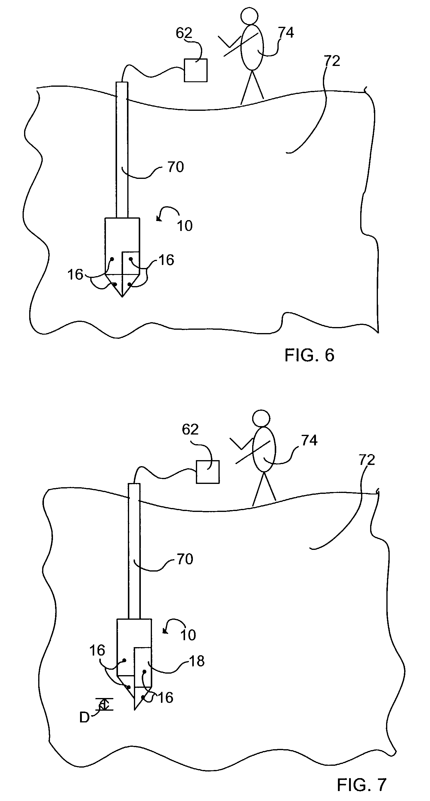
A method for modeling material behavior includes using empirical three dimensional non-uniform stress and strain data to train a self-organizing computational model such as a neural network. A laboratory device for measuring non-uniform stress and strain data from material includes an enclosure with an inclusion in it. As the enclosure is compressed, the inclusion induces a non-uniform state of stress and strain. A field testing device includes a body having a moveable section. When the body is inserted in a material and the moveable section moved, a non-uniform state of stress and strain can be characterized.

Description

PRIORITY CLAIM[0001]This application claims priority of U.S. Provisional Application Ser. No. 60 / 371,095, filed Apr. 9, 2002 under 35 U.S.C. §119.STATEMENT OF GOVERNMENT INTEREST[0002]This invention was made with Government assistance under National Science Foundation Grant No. MSS 92-14910, National Science Foundation Grant No. CMS 95-08462 and National Science Foundation Grant No. CMS 00-84556. The government has certain rights in the invention.FIELD OF THE INVENTION[0003]The present invention is related to methods and systems for modeling material behavior, including methods and systems for modeling stress and strain effects in soil.BACKGROUND OF THE INVENTION[0004]In current engineering practice, the design and construction of structures such as tunnels, underground sewers, underground parking garages, foundations, buildings, and the like often begin with a characterization of the engineering response of soil due to the proposed construction. A numerical model may be used to pre...

Claims


Application Information

Patent Timeline
Patent Type & Authority Patents(United States)
IPC IPC(8): G06F17/10E02D1/02G01L5/00G05B13/02G05B17/02G06F17/50
CPCE02D1/022G01L5/0004G01L5/008G05B13/027G05B17/02G06F17/5009G06F17/5018G06F30/23G06F30/20G06F2119/14
Inventor GHABOUSSI, JAMSHIDHASHASH, YOUSSEF M. A.PECKNOLD, DAVID
Owner THE BOARD OF TRUSTEES OF THE UNIV OF ILLINOIS
Learn More