
Method for detecting the cleanliness of a filter

a filter and cleanliness technology, applied in the field of filter cleanliness detection, can solve the problems of affecting the operation efficiency of the electronic device, and affecting so as to achieve the effect of affecting the ventilation effect of the fan and the cleanliness of the filter

Inactive Publication Date: 2008-11-04
QISDA CORP
View PDF6 Cites 48 Cited by
  • Summary
  • Abstract
  • Description
  • Claims
  • Application Information

AI Technical Summary

Benefits of technology

The invention provides a method for detecting the cleanliness of a filter on a fan. The method uses the actual rotation rate of the fan and the rotation control voltage to calculate the actual dust value of the filter. This allows the user to be reminded to clean the filter to prevent blockages and maintain the ventilation effect of the fan. The technical effect of this invention is to provide a convenient and effective way to maintain the cleanliness of filters on fans.

Problems solved by technology

When the fan rotates, dusts tend to deposit on the filter.
When too many dusts are deposited on the filter, airflow that flow through the filter will become smaller.
Consequently, the fan will be unable to ventilate the heat outside the electronic device, severely affecting the operation efficiency of the electronic device.
Unless the user clean the filter periodically, otherwise it is not easy to be aware that the filter needs to be cleaned or replaced because too many dusts have deposited on the filter.
Especially for the filter deposited inside the electronic device, the user cannot gain any knowledge of the cleanliness of the filter just by observing the appearance of the electronic device, unless the electronic device is disassembled and checked.
However, such an inspection is very troublesome to the user.

Method used


Image

  • Method for detecting the cleanliness of a filter
  • Method for detecting the cleanliness of a filter
  • Method for detecting the cleanliness of a filter

Examples


Embodiment Construction

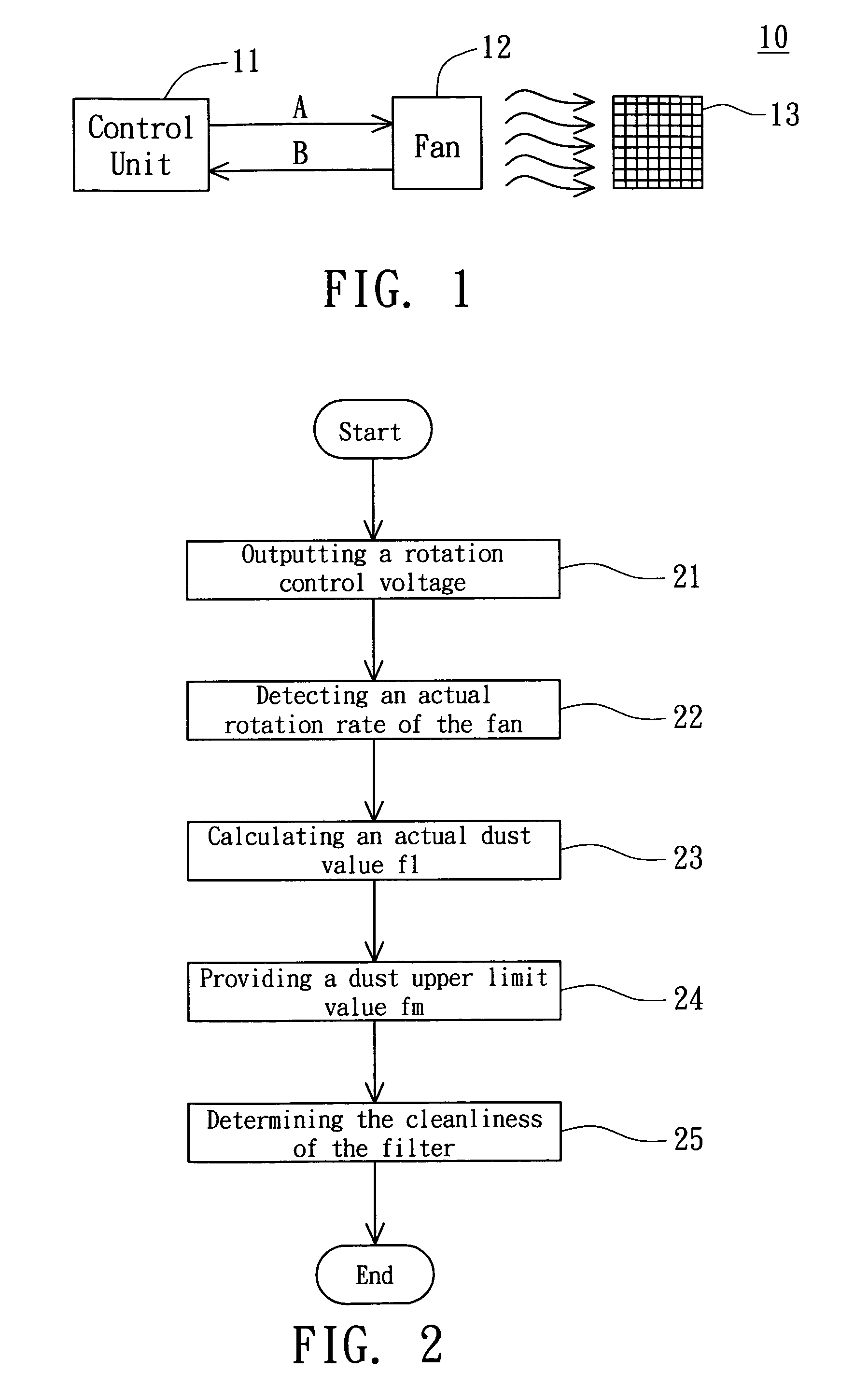
[0016]Referring to FIG. 1, a diagram of an electronic device according to a preferred embodiment of the invention is shown. In FIG. 1, the electronic device 10 at least includes a control unit 11, a fan 12 and a filter 13. The control unit 11 outputs a rotation control voltage A to the fan 12, wherein the rotation control voltage A corresponds to a pre-set rotation rate. After receiving the rotation control voltage A, the fan 12 starts to rotate, meanwhile, the control unit 11 detects an actual rotation rate B of the fan 12. The filter 13 is disposed on an air outlet or air inlet of the fan 12, wherein the airflow generated by the rotation of the fan 12 flows through the filter 13. The control unit 11 determines the cleanliness of the filter 13 according to the actual rotation rate B and the rotation control voltage A.

[0017]Referring to FIG. 2, a flowchart of a method for detecting the cleanliness of a filter according to a preferred embodiment of the invention is shown. Refer to FI...


PUM

PropertyMeasurementUnit
rotation rateaaaaaaaaaa
rotationaaaaaaaaaa
rotation pulse frequencyaaaaaaaaaa

Abstract

A method for detecting the cleanliness of a filter. The filter is disposed on an air inlet or an air outlet of a fan. The method includes the following steps. At first, outputting a rotation control voltage to the fan, and an airflow generated by the rotation of the fan flows through the filter. Then, detect an actual rotation rate of the fan, and calculate an actual dust value f1 according to the actual rotation rate and the rotation rate control voltage. Then, a dust upper limit value of the filter is defined. Finally, the cleanliness of the filter is determined according to the actual dust value and the dust upper limit value.

Description

[0001]This application claims the benefit of Taiwan application Serial No. 93105009, filed Feb. 26, 2004, the subject matter of which is incorporated herein by reference.BACKGROUND OF THE INVENTION[0002]1. Field of the Invention[0003]The invention relates in general to a method for detecting the cleanliness of a filter, and more particularly to a method for determining the cleanliness of the filter according to a rotation control voltage received by the fan and an actual rotation rate outputted by the fan.[0004]2. Description of the Related Art[0005]Living in modern age with rapid advance and continual renovation in technology, electronic device has become an indispensable appliance to modern people in their everyday life. The ventilation quality of an electronic device such as desktop computer, notebook computer or projector has much to do with the stability of system operation and the lifespan of the product. Taking the notebook computer for example, in order to ventilate the heat...

Claims


Application Information

Patent Timeline
Patent Type & Authority Patents(United States)
IPC IPC(8): B01D39/00B01D46/00B01D46/44B01D46/46
CPCB01D46/444B01D46/0086
Inventor HSIEH, CHIA-CHANGWEI, HUNG-JEN
Owner QISDA CORP
Learn More