
Method to improve iron production rate in a blast furnace

a technology of blast furnace and production rate, which is applied in the direction of blast furnaces, furnace types, furnaces, etc., can solve the problems of affecting the stability of the melting zone and furnace hearth, affecting gas flow, and delaying further reduction and melting, so as to improve the melting behaviour of iron ore pellets and reduce alkali circulation , the effect of maximizing the reactive mineral surface area

Inactive Publication Date: 2008-10-28
LOUSSAVAARA KIIRUNAVAORA AB
View PDF15 Cites 5 Cited by
  • Summary
  • Abstract
  • Description
  • Claims
  • Application Information

AI Technical Summary

Benefits of technology

"The invention is a method to improve the production of iron in a blast furnace by coating iron-containing material with a slag-modifying material before charging it into the blast furnace. The coating can be applied to green pellets or fired pellets. The coating can be made with a variety of minerals that have specific properties in the blast furnace process. The coated pellets have advantages such as improved gas-solid reactions, reduced dusting, and improved slag formation. The coating can also be used to reduce alkali circulation and improve the distribution of slag in the blast furnace. The coated pellets can be transported and handled with less moisture and have reduced dust output. The coating can be applied using a dispersion containing specific minerals that can capture alkali and limit its reaction with coke or deposit on the refractories. The dispersion can also contain fine particulate solids with controlled grain sizes and different surface polarization to improve adherence to the pellet surface and reduce dusting in transport and output via the blast furnace top gas."

Problems solved by technology

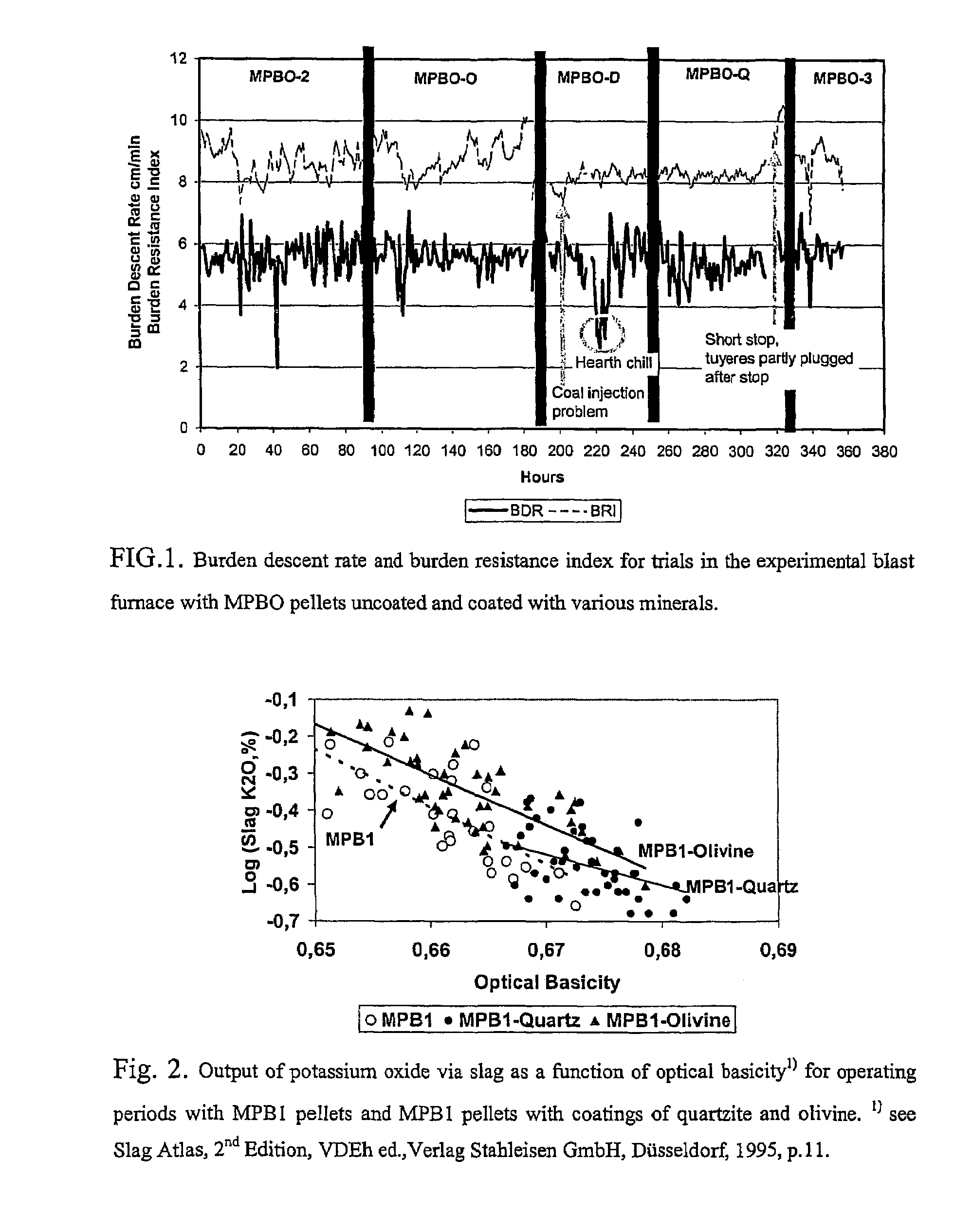
It has been found that this melting process—including slag and iron meltdown and carburisation—affects greatly the stability in the melting zone and hearth of the furnace, and can affect gas flow.
In some instances, due to the endothermic reduction of FeO and melting of iron, slags may refreeze blocking gas flow through the ore layer and delaying further reduction and melting.
These depositions are known to cause scaffolding, hanging and also react with the refractory lining of the furnace.
Also, the presence of alkali in reducing gas has been shown to cause degradation of coke and iron ore agglomerates which results in permeability problems in the packed bed.
The phenomena of clustering of ores, poor slag formation and meltdown behaviour and alkali circulation result in less efficient gas-solid contact, unstable burden descent and unstable hot metal quality requiring a higher blast furnace fuel rate that results in a lower productivity.
Alkalis circulating in the form of carbonates or cyanides deposit in the shaft to block gas flow, cause scaffolds to form on the walls, clustering of the ore layers, and react with coke or agglomerates causing degradation.
Due to the low surface of bulk additives, the reaction with alkalis is not maximised.
Secondly, when the agglomerates begin to melt down, acidic slags are the first to flow from iron ore agglomerates.
However, due to the heterogeneous distribution of the fluxing particles extreme slag compositions may be present resulting in high viscosity slags blocking gas flow and potentially causing clustering of pellets, or in worst case, refreezing of slag causing extreme channelling of gas and hanging.
Moisture in the pellets is to be avoided as it depresses blast furnace top gas temperatures which in some cases requires more fuel and therefore lowers blast furnace productivity.
Such dusts, commonly called flue dusts, are both a loss of iron units and expensive to dispose of or recycle.

Method used


Image

  • Method to improve iron production rate in a blast furnace
  • Method to improve iron production rate in a blast furnace

Examples


Embodiment Construction

[0030]The present invention relates to a method to improve iron production in a blast furnace being charged by iron containing agglomerates comprising contacting the chargeable iron containing material with a slag modifying effective amount of a dispersion of a particulate material. Said contacting occurring after iron ore agglomeration and prior to charging to the blast furnace shaft.

[0031]The chargeable agglomerated material of the present invention may be in any form that is typical for processing in a blast furnace. For non-limiting example, the chargeable material may be ores agglomerated to pellets, briquettes, granulates etc., or natural agglomerated iron oxide ores typically referred to as lump ore or rubble ore.

[0032]As used herein, “dispersion” means any distribution or mixture of fine, finely divided and / or powdered solid material in liquid medium. The similar terms “slurry”, “suspension”, etc. are also included in the term “dispersion”.

[0033]As used herein, “slag modifyi...


PUM

PropertyMeasurementUnit
temperaturesaaaaaaaaaa
particle sizeaaaaaaaaaa

Abstract

The present invention relates to a method to improve the iron production rate in a blast furnace being charged by iron containing agglomerates. The method includes contacting the chargeable iron containing material with a slag modifying effective amount of a dispersion of a particulate material, wherein the contacting occurs prior to the charging of the agglomerate to blast furnace process.

Description

[0001]This application is a US national phase of international application PCT / SE03 / 00767 filed in English on 12 May 2003, which designated the US and claims priority to SE Application No. 0201453-8, filed 10 May 2002, each incorporated herein by reference in its entirety.[0002]The present invention relates to a method to improve iron production rate in a blast furnace in accordance with the preamble of claim 1.BACKGROUND OF THE INVENTION[0003]This invention relates generally to affecting reactions between blast furnace gas and minerals present in the blast furnace shaft, and relates to the distribution of minerals with relation to the formation of molten slag. There are also factors related to dust suppression in iron ore agglomerate handling and transport.[0004]Iron oxide pellets are normally used alone or together with natural lump ores or sinter as iron units in blast furnaces. In the high temperature region of the furnace, above approximately 1000° C., reduction of iron oxide t...

Claims


Application Information

Patent Timeline
Patent Type & Authority Patents(United States)
IPC IPC(8): C21B3/02C22B1/04C22B1/16C21B5/00C21B5/04C22B1/243
CPCC21B5/001C21B5/04C22B1/243C21B15/04C22B1/24
Inventor STERNELAND, JERKERHOOEY, LAWRENCE
Owner LOUSSAVAARA KIIRUNAVAORA AB
Learn More