
Connector

a technology of connecting rods and connectors, applied in the direction of connecting rods, electrical appliances, coupling devices, etc., can solve the problems of poor operation efficiency, difficult to achieve compact design, difficult to positively effect a double lock, etc., to achieve good operation efficiency, simple structure, and improve productivity

Inactive Publication Date: 2008-10-28
YAZAKI CORP
View PDF14 Cites 9 Cited by
  • Summary
  • Abstract
  • Description
  • Claims
  • Application Information

AI Technical Summary

Benefits of technology

[0008]This invention has been made in view of the above circumstances, and an object of the invention is to provide a connector in which a positive double lock can be secured, and besides the efficiency of an operation is enhanced, and furthermore a compact design can be achieved.
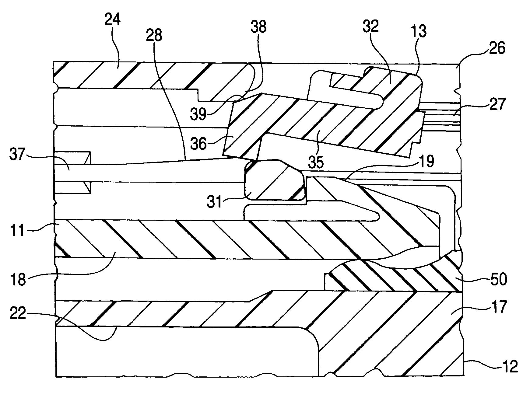
[0010]In the invention of the above Paragraph 1) the fitting-ensuring member is dropped through the abutment portion to hold the elastic lock arm against elastic deformation. Therefore, the fitting-ensuring member differs from the conventional fitting detection member in that the conventional fitting detection member is slid while its distal end portion is much elastically deformed. Therefore, the double lock can be effected with the simple operation without requiring a large inserting force. And besides, the fitting-ensuring member has no elastic detection arm (as in the conventional construction) which is advanced while being elastically deformed, and therefore the double lock can be effected in a space-saving manner. Therefore, the positive double lock can be secured, and besides the efficiency of the operation can be enhanced, and furthermore the compact design can be achieved.
[0012]In the invention of the above Paragraph 2), when the engagement portion of the fitting-ensuring member is to be brought into engagement with the lock portion of the elastic lock arm through the abutment portion, the fitting-ensuring member slides past the retaining projection of the male connector housing and the lock portion of the elastic lock arm. Therefore, the fitting-ensuring member can lock the retaining projection and the lock portion together in a double manner with the simple structure, and a mold of a complicated shape is not required, and therefore the productivity can be enhanced.
[0013]The connector of the invention can solve the problems that it is difficult to secure a positive double lock, that the efficiency of the operation is not good and that it is difficult to achieve a compact design, and therefore there are obtained advantages that the positive double lock can be secured, that the efficiency of the operation can be enhanced and that the compact design can be achieved.

Problems solved by technology

As a result, a large inserting force is required, and therefore it is difficult to positively effect a double lock, and the efficiency of the operation is not good.
And besides, since the elastic detection arm 102 is advanced while being elastically deformed, the elastic detection arm 102 need to have a relatively large length, and this makes it difficult to achieve a compact design.

Method used


Image

  • Connector
  • Connector
  • Connector

Examples


Embodiment Construction

[0021]A preferred embodiment of the present invention will now be described in detail with reference to the drawings.

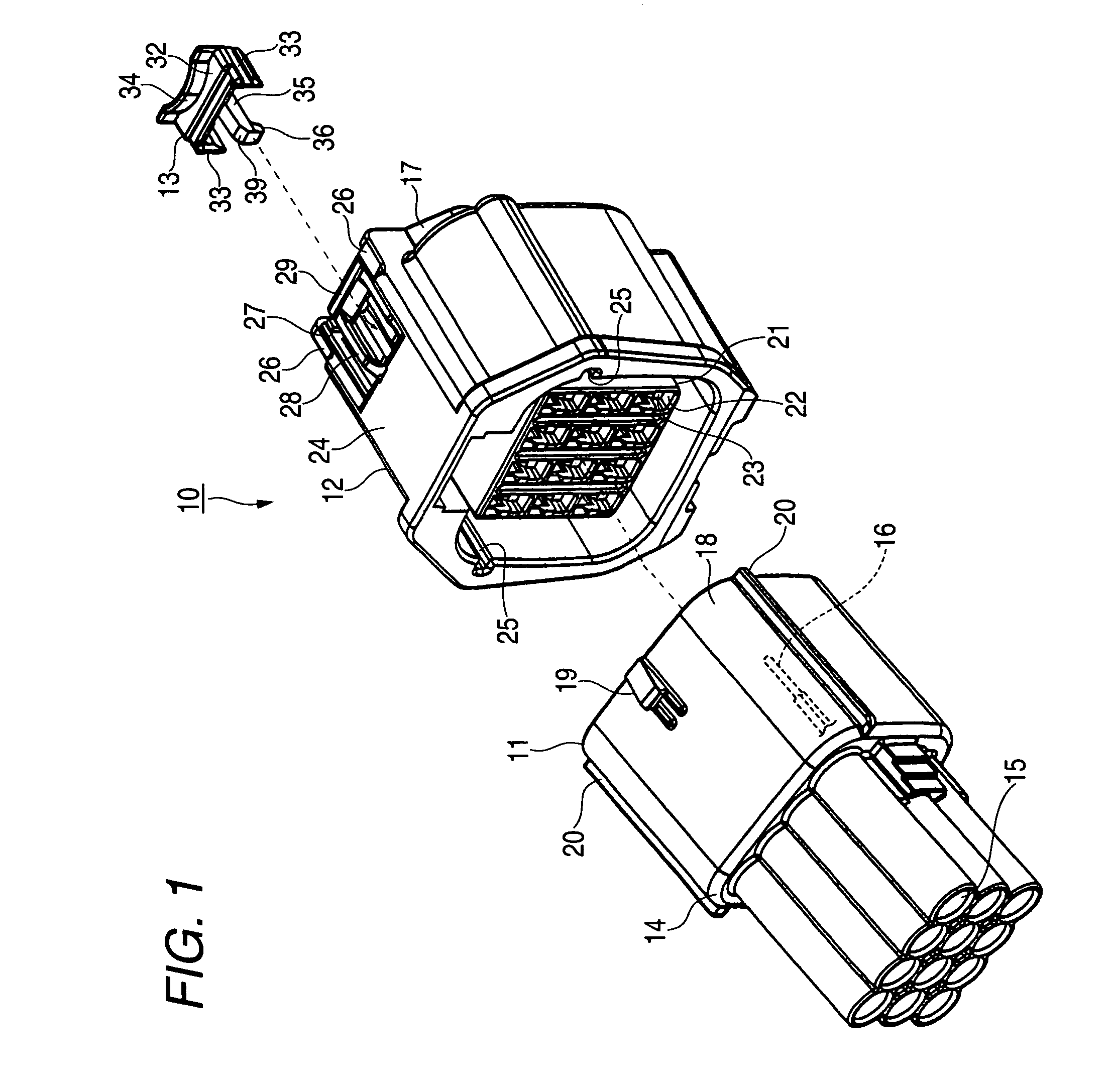
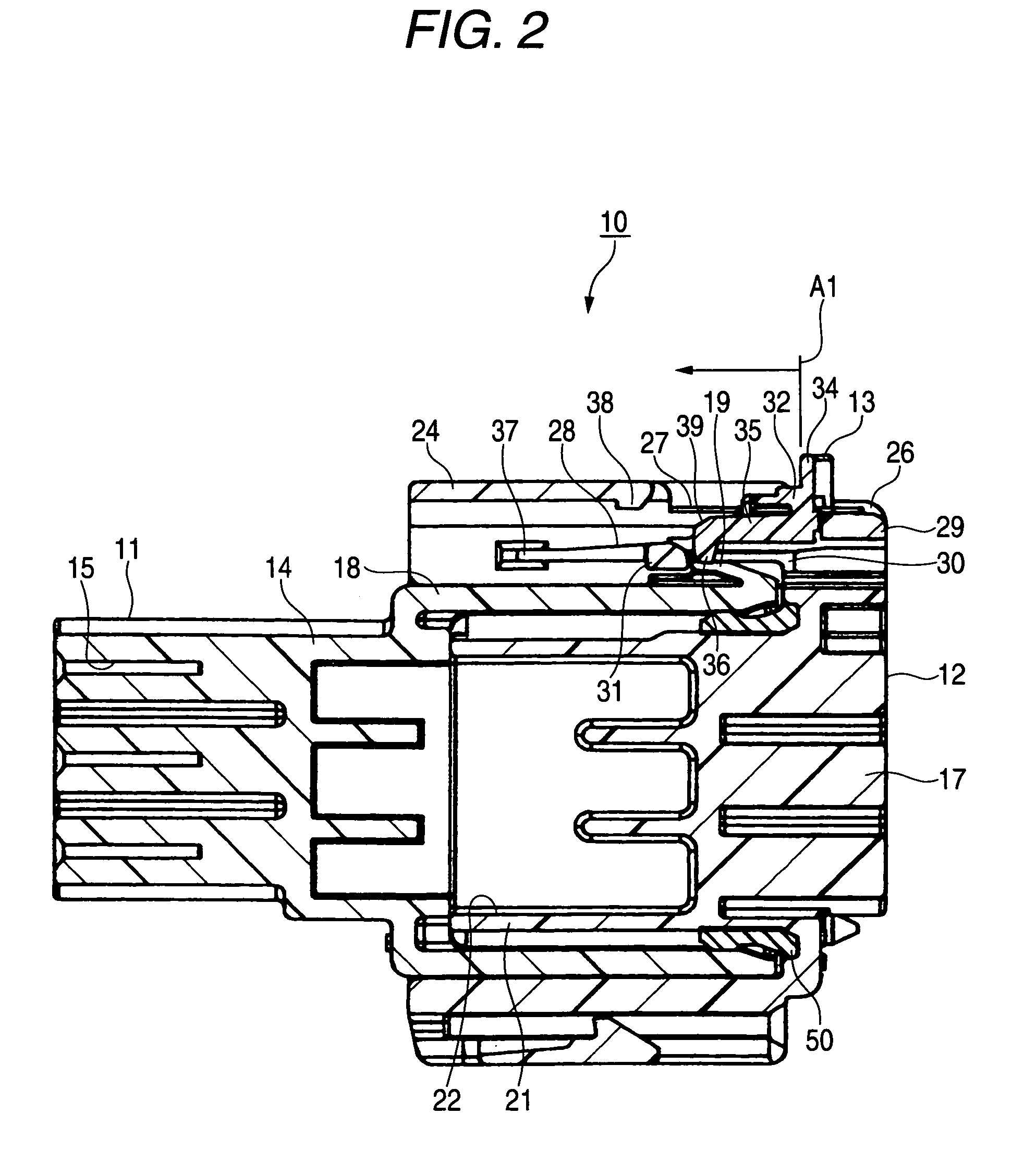
[0022]FIG. 1 is an exploded, perspective view of one preferred embodiment of a connector of the invention, FIG. 2 is a vertical cross-sectional view of the connector of FIG. 1, showing a fitting-ensuring member in a provisionally-retained condition, FIG. 3 is a vertical cross-sectional view of the connector of FIG. 1, showing a first half of a process of shifting of the fitting-ensuring member from the provisionally-retained condition to a completely-retained condition, FIG. 4 is an enlarged view of an important portion, showing a second half of the shifting process of FIG. 3, and FIG. 5 is a vertical cross-sectional view of the connector of FIG. 1, showing the fitting-ensuring member in the completely-retained condition.

[0023]As shown in FIG. 1, one preferred embodiment of the connector 10 of the invention comprises a male connector 11, a female connector 12, and the...


PUM


Abstract

A connector 10 includes a male connector housing 14 having a retaining projection 19, a female connector housing 17 having an elastic lock arm 28 which is brought into retaining engagement with the retaining projection 19 when the male connector housing 14 is inserted and fitted into the female connector housing, and a fitting-ensuring member 13 which is brought into engagement with the elastic lock arm 28, retainingly engaged with the retaining projection 19, to hold the elastic lock arm 28 against elastic deformation. An abutment portion 38 is formed at one of the female connector housing 17 and the fitting-ensuring member 13, and during the movement of the fitting-ensuring member 13, the abutment portion 38 causes the fitting-ensuring member 13 to drop into the elastic lock arm 28.

Description

BACKGROUND OF THE INVENTION[0001]1. Field of the Invention[0002]This invention relates to a connector in which an elastic lock arm formed on a connector housing is held against elastic deformation by a fitting-ensuring member, thereby locking the fitted male and female connector housings together in a double manner.[0003]2. Description of the Related Art[0004]There is known one conventional connector in which when a male connector housing and a female connector housings are provisionally retained relative to each other, a retaining projection of a fitting detection member is engaged with a lock projection of the male connector housing (see, for example, JP-A-9-219255 Publication (FIGS. 1 to 5)).[0005]In the connector 100 disclosed in Patent Literature 1, the fitting detection member 101 has an elastic detection arm 102 for an abutment projection 111 of the male connector housing 110. When the fitting detection member 101 is pushed in a connector fitting direction, the elastic detect...

Claims


Application Information

Patent Timeline
IPC IPC(8): H01R13/627
CPCH01R13/6272H01R13/639
Inventor KUWAYAMA, YASUMICHI
Owner YAZAKI CORP
Learn More