Steering wheel tilt device

a technology of steering wheel and tilt device, which is applied in the direction of mechanical control device, process and machine control, instruments, etc., can solve the problems of radial load, inapplicability of the method to vehicles without such a mechanism, and the driver's difficulty in getting on or off, etc., to achieve suppressed backlash, small force, and large force

Active Publication Date: 2008-10-28
WORKS BELL
View PDF10 Cites 2 Cited by
  • Summary
  • Abstract
  • Description
  • Claims
  • Application Information

AI Technical Summary

Benefits of technology

[0009]The present invention has been made in view of the foregoing circumstances, and it is therefore an object of the invention to strengthen the coupling between a steering wheel and a steering boss and reduce the degree of backlash by using a ball and a ball receiving dent to couple the steering wheel to the steering boss and increasing the pressure applied to the ball, and to provide smooth coupling between the steering wheel and the steering boss by holding the ball from inside as a coupling member tending to protrude from a tapered hole and smoothly guiding the ball into a recess for coupling in coupling the steering wheel to the steering boss.
[0022]According to a first aspect of the present invention, the socket and the plug can make a hinge movement due to the existence of the first rotational shaft. Thus, the steering wheel can be tilted up, so the driver is allowed to get on or off easily. According to the present invention, a force is applied from the first spring member to the sleeve arm perpendicularly toward the plug in fitting the socket to the plug, so a larger force can be applied to the ball as the coupling member than in the case of conventional products. When the socket and the plug are fitted to each other, a part of the sleeve arm presses the ball due to the force of the first spring member. Owing to this pressure, the ball is pressed by a part of the recess of the plug and a part of the tapered hole. As a result, three-point fixation with a large force can be realized. Thus, secure coupling is achieved, and backlash can be suppressed.
[0023]According to an other aspect of the present invention, the ball is prevented from protruding from the small-diameter hole due to the recess for accommodating part of the ball. Therefore, when the socket and the plug are fitted to each other through a rotational movement, the ball does not interfere with the projection member of the plug. Consequently, smooth coupling is made possible.
[0024]According to a still other aspect of the present invention, after the projection member of the plug has come into contact with an inner cam, the inner cam is pushed up to stop the ball from being held by the inner cam. The ball, which can now move toward the inner cam, is thrust out of the tapered hole due to a pressure applied from the sleeve arm. Thus, the sleeve arm rotates toward the plug and the ball is prevented from being thrust out toward the small-diameter hole until the inner cam is pushed up. Therefore, the ball to which a pressing force is applied from the sleeve arm need not be thrust out toward the large-diameter hole during rotation, and rotation for fitting the socket to the plug is made possible with a small force. When the inner cam is pushed up, the ball receiving dent of the projecting portion appears subsequently to the inner cam. Therefore, the protruding ball smoothly enters the ball receiving dent. As a result, secure coupling can be achieved without a large force.
[0025]According to a still other aspect of the present invention, a dead pin is in a dead pin hole arranged in the projection member in fitting the socket to the plug. Therefore, the sleeve arm cannot be rotated in releasing the socket from the plug, unless the safety trigger is pulled to remove the dead pin from the dead pin hole. Thus, the sleeve arm is prevented from rotating unexpectedly to release the socket from the plug. Consequently, the steering wheel can be operated safely.

Problems solved by technology

Thus, the driver finds it difficult to get on or off.
Thus, this method is not applicable to vehicles unequipped with such a mechanism, for example, sports utility vehicles and the like.
Thus, the occurrence of backlash results from a radial load in steering the steering wheel when the two components are coupled together.
However, after having removed the steering wheel and got off, the driver must bother to carry the steering wheel about or mount it again.
In this construction, however, when a force for holding a ball is increased to suppress backlash, a large force is required to disconnect the steering wheel, which makes opening / closing movements thereof difficult.
When the force for holding the ball is reduced to facilitate the opening / closing movements, backlash is caused.

Method used


Image

  • Steering wheel tilt device
  • Steering wheel tilt device
  • Steering wheel tilt device

Examples


first embodiment

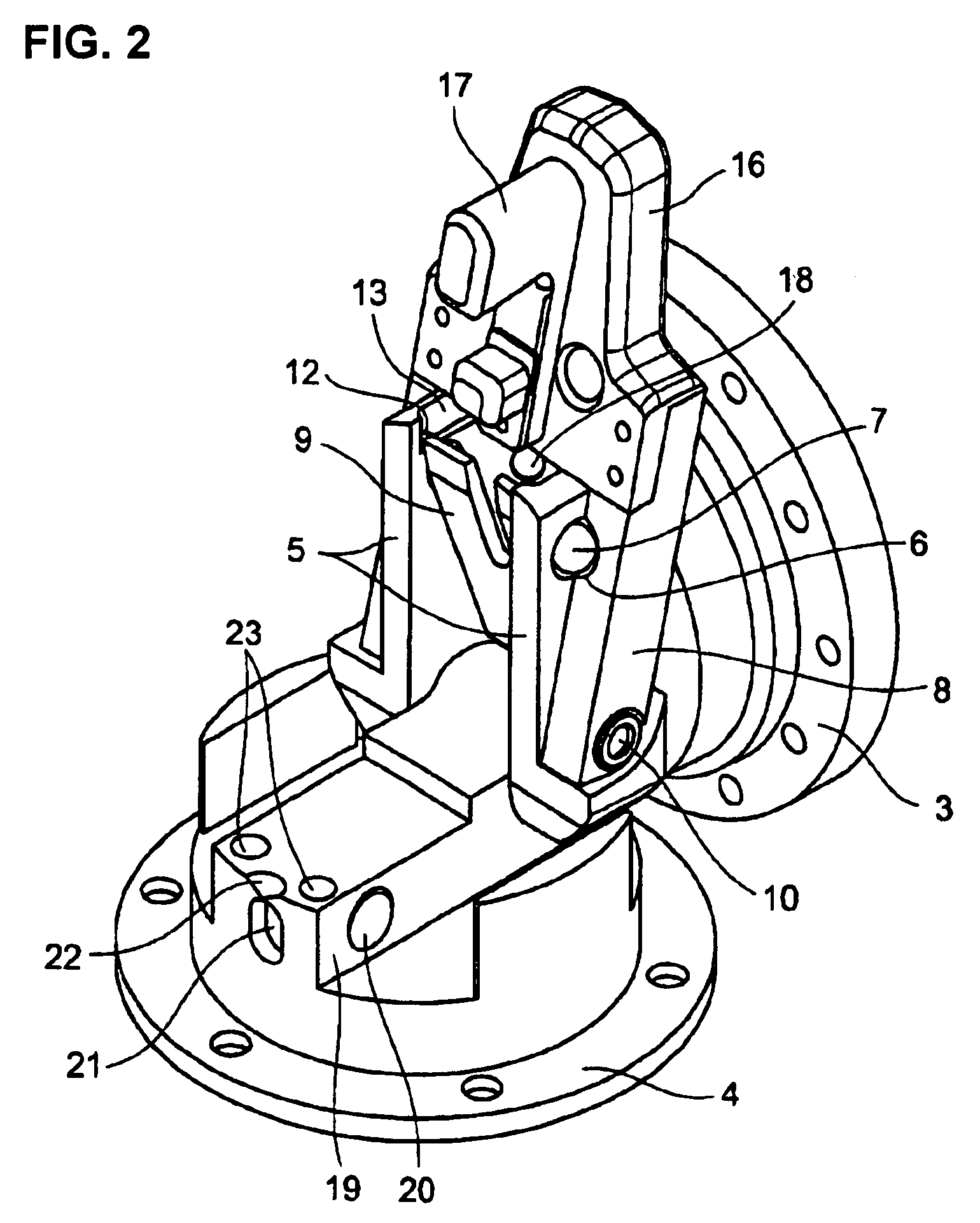
[0044]FIGS. 1A to 1C are explanatory views each showing a mode of use of the steering wheel tilt device according to the present invention. FIG. 2 is an outline view of a tilted state of the steering wheel tilt device. FIG. 3 is an outline view of a fitted state of the steering wheel tilt device. FIG. 4 is a lateral view of the steering wheel tilt device. FIG. 5 is a lateral cross-sectional view of the steering wheel tilt device. FIG. 6 is a cross-sectional view taken along a line A-A″ of FIG. 4. FIG. 7 is an enlarged view of a region B of FIG. 6. FIGS. 8A to 8E are transitional views of tilt-up operations from a fitted state of the steering wheel tilt device. FIG. 9 is a cross-sectional view taken along a line D-D″ of FIG. 8A. FIGS. 10A to 10C are step views of coupling operations from a tilted state of the steering wheel tilt device. FIG. 11 is a lateral view of left and right sleeve arms as viewed from inside. FIG. 12A is a lateral view of a projecting portion. FIG. 12B is a cros...

second embodiment

[0066]A steering wheel tilt device according to the second embodiment of the present invention will be described with reference to FIGS. 13A and 13B. FIG. 13A is a lateral cross-sectional view in this embodiment of the present invention. Referring to FIG. 13A, in the vicinity of the first rotational shaft 30, a hole 29 and two through-holes 25 are arranged on the socket 3 side and the plug 4 side respectively. FIG. 13B is a cross-sectional view taken along a line E-E″. Referring to FIG. 13B, grub screws 28 are in the hole 29. Balls 27 for giving resistance to rotation and a coil 26 are disposed in the through-hole 25. The steering wheel tilt device according to the second embodiment of the present invention is obtained by providing the steering wheel tilt device according to the first embodiment of the present invention with a construction for stopping the socket 3 in its open state at an arbitrary position desired by an operator.

[0067]First, the through-holes 25 are opened in the p...

third embodiment

[0070]A steering wheel tilt device according to the third embodiment of the present invention is obtained by providing the steering wheel tilt device according to the first embodiment of the present invention with a construction for removing the socket 3 from the plug 4.

[0071]A bolt is used as the center of the first rotational shaft 30 when the socket 3 and the plug 4 make a hinge movement. In this embodiment of the present invention, a projecting portion is cut open outward in a hole for supporting the bolt. Thus, the socket 3 can be removed from the plug 4 after the steering wheel 1 has been tilted up.


PUM


Abstract

Desired is a function of tilting up a steering wheel to allow a driver to get on or off easily. An object of the invention is to strengthen the coupling between a steering wheel and a steering boss and reduce the degree of backlash by using a ball and a ball receiving dent to couple the steering wheel to the steering boss and increasing the pressure applied to the ball, and to provide smooth coupling between the steering wheel and the steering boss by holding the ball from inside as a coupling member tending to protrude from a tapered hole and smoothly guiding the ball into a recess for coupling.

Description

BACKGROUND OF THE INVENTION[0001]I. Field of the Invention[0002]The present invention relates to a steering wheel tilt device having a function of tilting up a steering wheel to allow a driver to get on or off easily.[0003]II. Description of the Related Art[0004]Up to now, a steering wheel of a vehicle is fixed, and a lower portion of the steering wheel interferes with a leg of a driver when the driver gets on or off. Thus, the driver finds it difficult to get on or off. In order to solve this problem, therefore, there have been adopted a method of tilting up an entire steering including a steering shaft (see JP 2000-272524 A) and a method of tilting up only the steering wheel.[0005]However, according to the method of moving the entire steering including the steering shaft, a corresponding mechanism needs to be provided already in the initial phase of manufacture. Thus, this method is not applicable to vehicles unequipped with such a mechanism, for example, sports utility vehicles a...

Claims


Application Information

Patent Timeline
Patent Type & Authority Patents(United States)
IPC IPC(8): G05G1/10
CPCB62D1/10Y10T74/20852Y10T74/20858
Inventor ICHIKAWA, YASUAKI
Owner WORKS BELL
Why Eureka
Try Eureka