
State machine recognition and optimization

a state machine and optimization technology, applied in the field of programable devices, can solve the problems of state machines that are sometimes not recognized by the compilation software and the hardware implementation is typically much less efficient, so as to reduce the amount of state transition and output logic, and optimize the user design

Inactive Publication Date: 2008-10-21
ALTERA CORP
View PDF5 Cites 13 Cited by
  • Summary
  • Abstract
  • Description
  • Claims
  • Application Information

AI Technical Summary

Benefits of technology

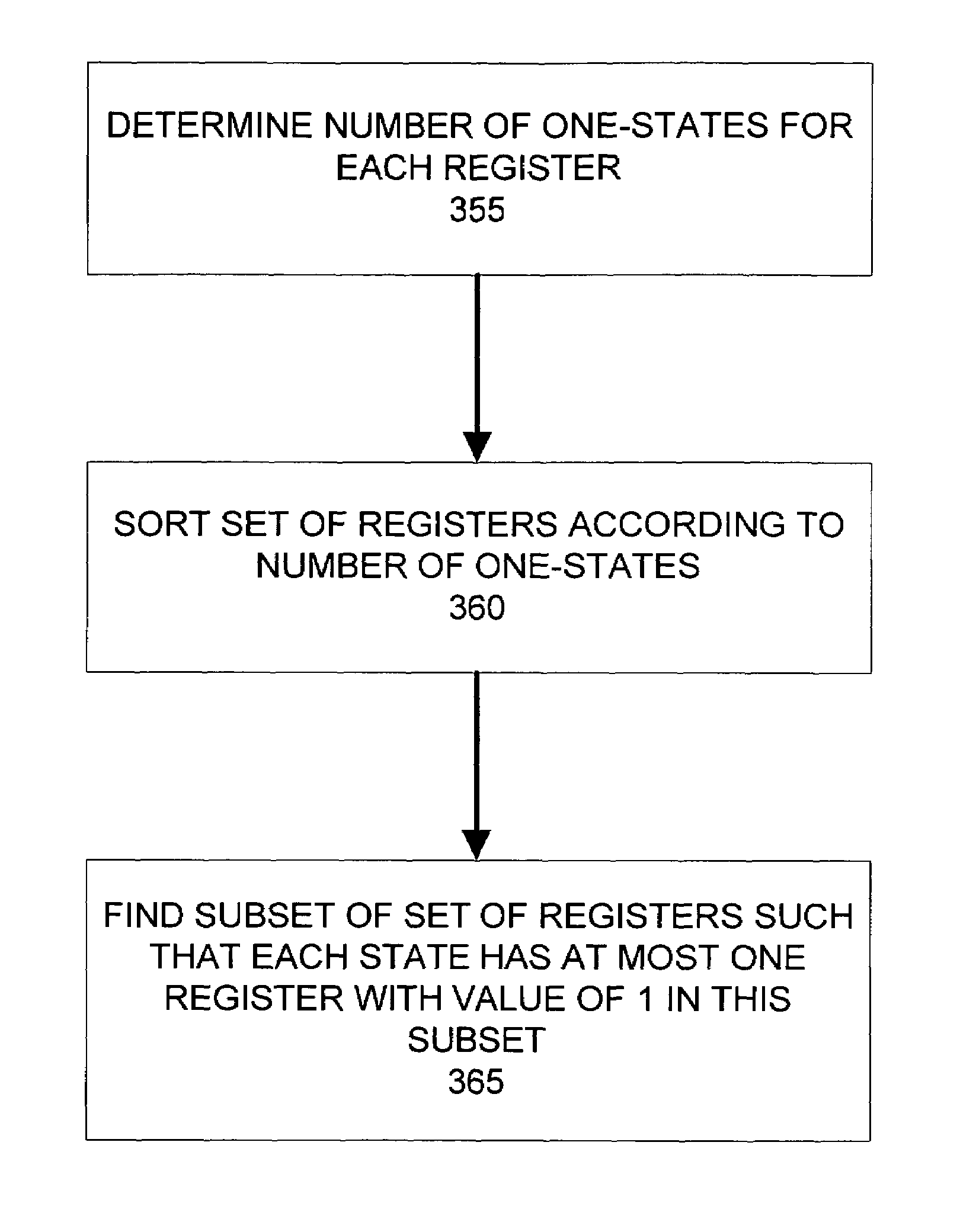
[0007]An embodiment of the invention identifies state machines from a netlist of circuit elements of a user design. Strongly connected components in the netlist are identified as candidates for analysis. The registers of each component are identified. An optimal set of inputs and potential state transition logic is identified in the component. A set of reachable states from an initial state of the registers of a component is determined by simulating state transitions in response to permutations of input values. State machine information is created to assist compilation software in optimizing the user design. Optimizations can include identifying redundant components based on the set of reachable states and reencoding the state machine with a different state encoding scheme to reduce the amount of state transition and output logic. A further embodiment searches for a subset of the set of reachable states representing a one-hot encoded state machine.

Problems solved by technology

Unfortunately, state machines are sometimes not recognized by the compilation software.
When the compilation software does not recognize the state machine, it does not know which states are explicitly defined for the state machine and which states are undefined and will never be used.
As a result, it must assume that all possible combinations of register values representing states may be used by the circuit, and the resulting hardware implementation is typically much less efficient.

Method used


Image

  • State machine recognition and optimization
  • State machine recognition and optimization
  • State machine recognition and optimization

Examples


Embodiment Construction

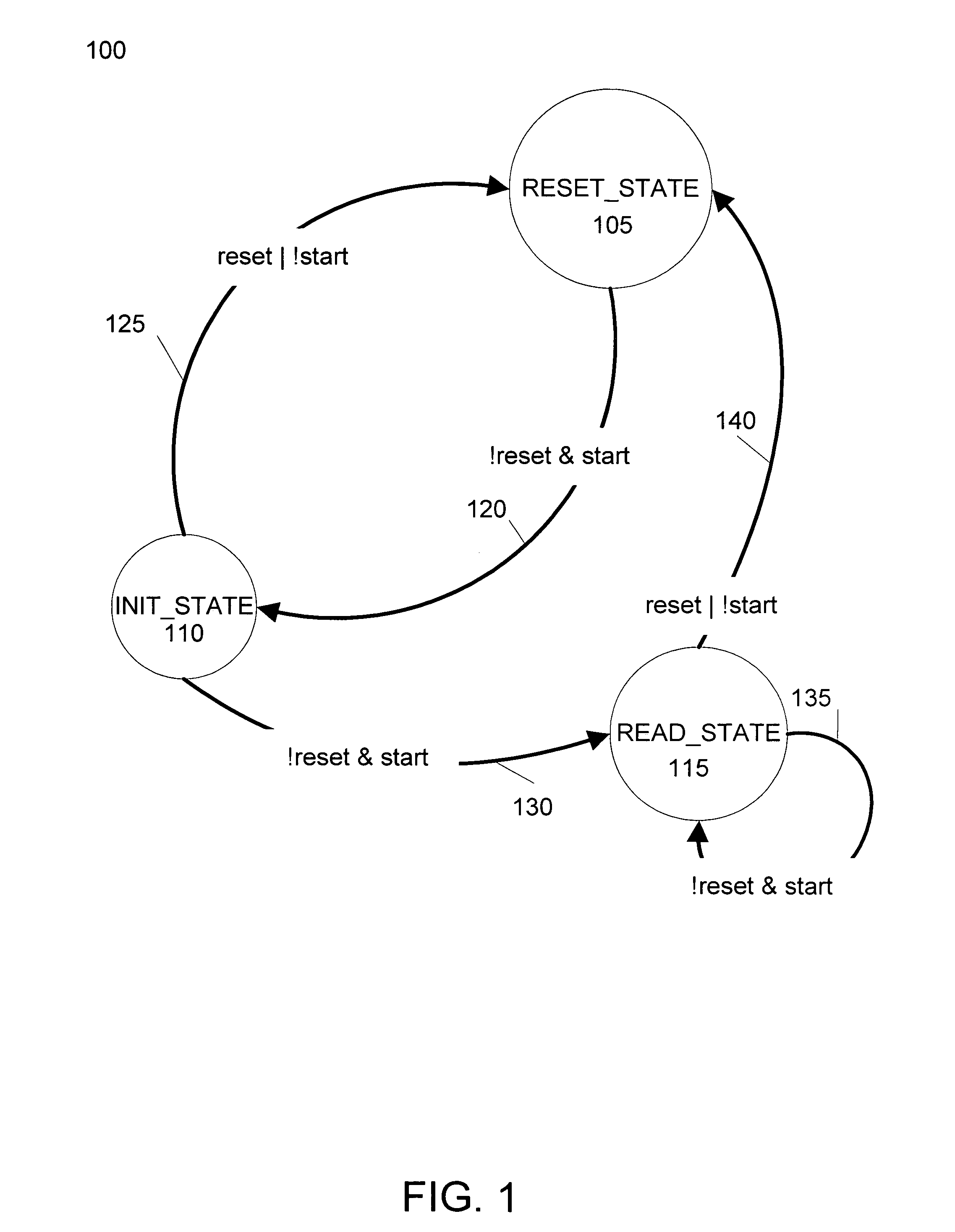
[0018]FIG. 1 is a state machine diagram illustrating the operation of an example state machine 100. State machine 100 includes three states: reset_state, 105; init_state, 110; and read_state, 115. State machine 100 includes transitions 120, 125, 130, 135, and 140. In this example, transitions between these states are controlled by Boolean expressions of two state machine inputs: reset and start. For example, the state machine 100 changes from reset_state 105 to init_state 110 when the reset input is 0 and the start input is 1. Although not shown in FIG. 1, the reset input may be asynchronous, so that the reset input can initiate a transition to the reset_state at any time, regardless of a clock signal. The other inputs can be synchronous, so that all other state transitions are synchronous with the clock signal.

[0019]When state machines are implemented in hardware, each state is associated a value in one or more registers, latches, flip-flops, or other devices capable of storing inf...


PUM


Abstract

State machines are identified from a netlist of circuit elements of a user design. Strongly connected components in the netlist are identified as candidates for analysis. The registers of each strongly connected component are identified. An optimal set of inputs and potential state transition logic is identified for the registers in the component. A set of reachable states from an initial state of the registers of a component is determined by simulating state transitions in response to permutations of input values. State machine information is created to assist compilation software in optimizing the user design. Optimizations can include identifying redundant circuit elements based on the set of reachable states and reencoding the state machine with a different state encoding scheme to reduce the amount of state transition and output logic. A subset of the set of reachable states representing a one-hot encoded state machine may be further isolated and optimized.

Description

BACKGROUND OF THE INVENTION[0001]The present invention relates to the field of programmable devices, and the systems and methods for programming the same. Programmable devices, such as FPGAs, typically includes thousands of programmable logic cells that use combinations of logic gates and / or look-up tables to perform a logic operation. Programmable devices also include a number of functional blocks having specialized logic devices adapted to specific logic operations, such as adders, multiply and accumulate circuits, phase-locked loops, and memory. The logic cells and functional blocks are interconnected with a configurable switching circuit. The configurable switching circuit selectively routes connections between the logic cells and functional blocks. By configuring the combination of logic cells, functional blocks, and the switching circuit, a programmable device can be adapted to perform virtually any type of information processing function.[0002]A typical compilation process fo...

Claims


Application Information

Patent Timeline
IPC IPC(8): G06F17/50
CPCG06F17/5045G06F30/30
Inventor VAN ANTWERPEN, BABETTEBAECKLER, GREGG WILLIAM
Owner ALTERA CORP
Learn More