
Plasma display panel having a magnesium oxide protective film and method for producing same

a protective film and magnesium oxide technology, applied in the manufacture of electrodes, electrode systems, electric discharge tubes/lamps, etc., can solve the problems of unstable discharge voltage, low brightness, and increase in discharge voltage, so as to reduce the amount of h2o and chx, stable discharge characteristics, and positive electrification of protective films

Inactive Publication Date: 2008-10-21
PANASONIC CORP
View PDF19 Cites 1 Cited by
  • Summary
  • Abstract
  • Description
  • Claims
  • Application Information

AI Technical Summary

Benefits of technology

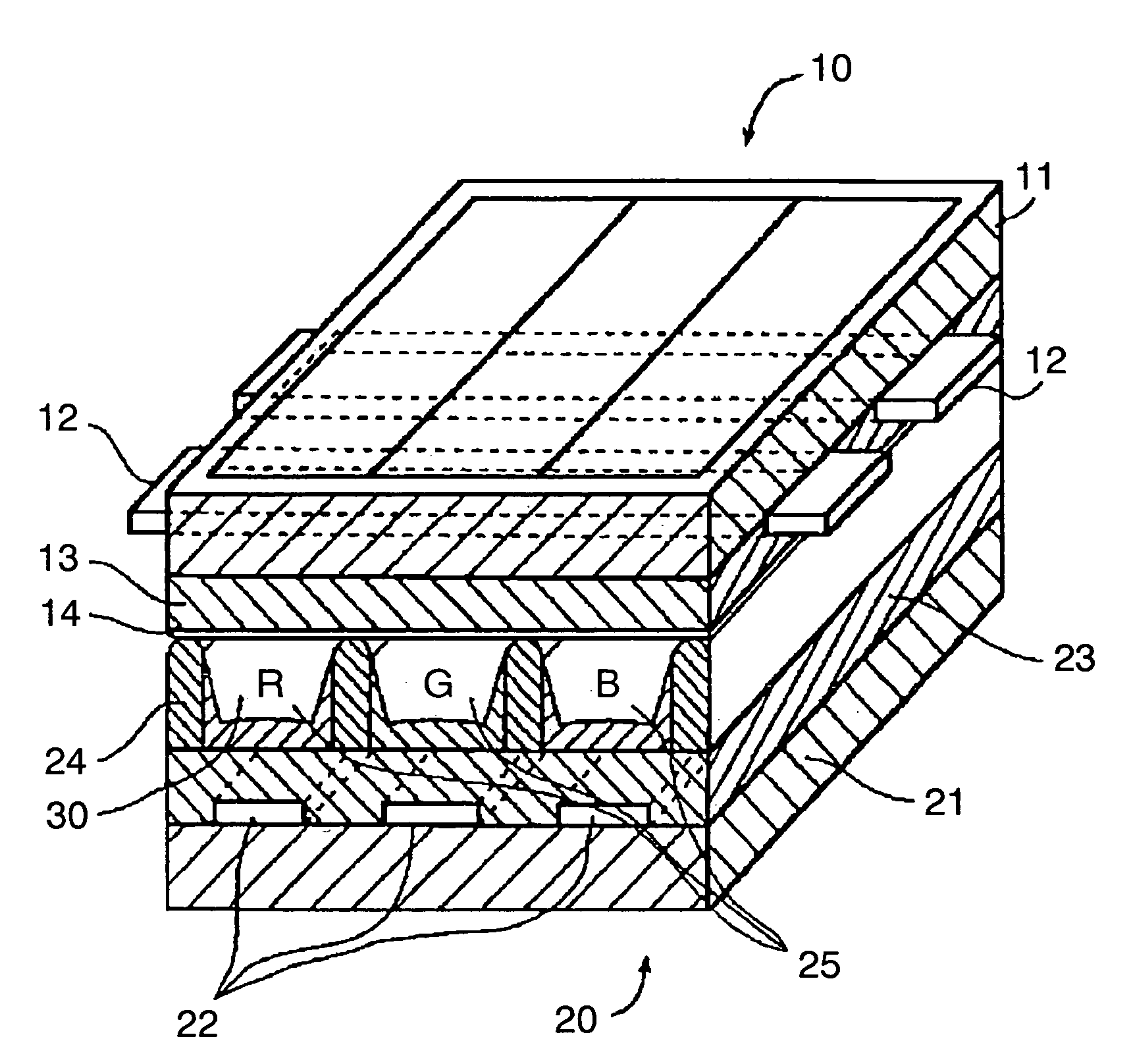
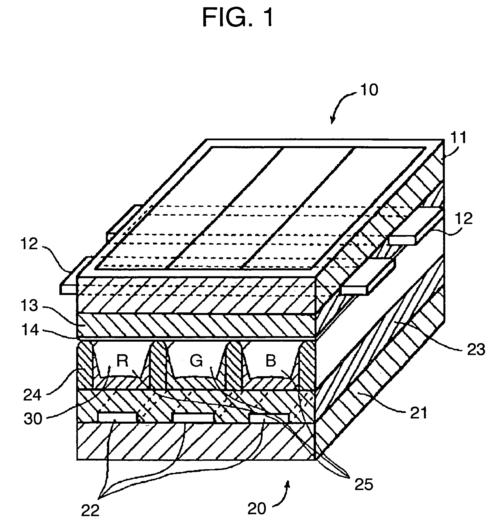
"The present invention provides a PDP with a stable discharge characteristic and low brightness degradation. The PDP includes a front panel and a back panel, where the front panel includes a first electrode on a first substrate, a dielectric glass layer covering the first electrode, and a protective film provided on the dielectric glass layer, made of magnesium oxide (MgO) with oxide added including an element with an electronegativity of 1.4 or higher. The back panel includes at least a second electrode on a second substrate, barrier ribs, and a phosphor layer. The protective film and the phosphor layer are arranged facing each other, and a discharge space partitioned with barrier ribs is formed between the front and back panels. The protective film is made of magnesium oxide (MgO) with oxide added including an element with an electronegativity of 1.4 or higher, which reduces the amount of H2O andCHx to be adsorbed to the protective film."

Problems solved by technology

Therefore, H2O, CO2, or a hydrocarbon gas (mostly, a resolvent from organic binders) generated in various processes of PDP manufacturing is adsorbed around the defects, causing discharge to be unstable and the discharge voltage to rise.
This causes oxidative and reducing reactions to non-crystallize the surface of the phosphor particles, resulting in a low brightness.

Method used


Image

  • Plasma display panel having a magnesium oxide protective film and method for producing same
  • Plasma display panel having a magnesium oxide protective film and method for producing same
  • Plasma display panel having a magnesium oxide protective film and method for producing same

Examples


embodiment

[0037]Hereinafter, a description is made for an embodiment according to the evaluation result of the sample produced with the above-mentioned method.

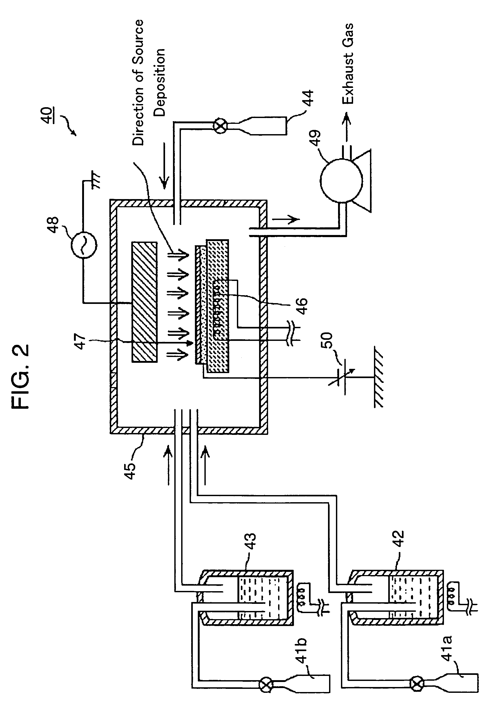
[0038]Table 1 shows the characteristic of a PDP for a case where various oxides including an element with a high electronegativity are added to the magnesium oxide (MgO) protective film, with its film-forming method changed. The PDP of sample No. 1 through No. 6 shown in table 1 has a magnesium oxide (MgO) protective film with an oxide added of an electronegativity of 1.4 or higher, made with the CVD method based on the above-mentioned embodiment. For the cell size of the PDP, according to a display for a 42-inch HDTV, the height of barrier rib 24 is set to 0.12 mm, and the clearance (cell pitch) between barrier ribs 24 is set to 0.15 mm, the structure of the barrier ribs is double-cross, where barrier ribs 24 are arranged in each cell, and the distance between discharge electrodes 12 is set to 0.06 mm. In addition, lead-based dielectri...


PUM

PropertyMeasurementUnit
pressureaaaaaaaaaa
distanceaaaaaaaaaa
distanceaaaaaaaaaa

Abstract

The present invention provides a plasma display panel that suppresses discharge sustain voltage, and reduces brightness degradation of a phosphor. In the plasma display panel, as protective film (14) made of magnesium oxide (MgO) formed on dielectric glass layer (13), protective film (14) made of magnesium oxide (MgO) with oxide added with an electronegativity of 1.4 or higher, is formed to suppress impure gas adsorption by protective film (14), stabilizes discharge sustain voltage, and reduces brightness degradation.

Description

[0001]This application is a U.S. National Phase application of PCT International application PCT / JP2004 / 005686.TECHNICAL FIELD[0002]The present invention relates to a plasma display panel to be used for a display device and the like, and to a method for producing the plasma display panel, especially to a highly efficient magnesium oxide (MgO) protective film for the panel.BACKGROUND ART[0003]In recent years, for color display devices used for image display such as in computers and television sets, a plasma display device using a plasma display panel (hereinafter, abbreviated as “PDP” or “panel”) receives attention as a large-size, thin, and lightweight color display device.[0004]An AC surface-discharge-type PDP, which is a representative AC type, has a front panel formed with a glass substrate where scan electrodes and sustain electrodes are arranged for surface discharge; and a back panel made of a glass substrate formed with data electrodes being arranged. The front and back panel...

Claims


Application Information

Patent Timeline
Patent Type & Authority Patents(United States)
IPC IPC(8): H01J17/49H01J9/02H01J9/00H01J11/12H01J11/22H01J11/24H01J11/26H01J11/34H01J11/40
CPCH01J9/02H01J11/12H01J11/40
Inventor AOKI, MASAKIKONDO, YUMISUGIMOTO, KAZUHIKOSETOGUCHI, HIROSHIHIBINO, JUNICHITANAKA, YOSHINORIHOSOKAWA, TEPPEI
Owner PANASONIC CORP
Learn More