
Roll-up barrier

a technology of rolling cage and roll-up rod, which is applied in the direction of door/window protective devices, curtain suspension devices, doors, etc., can solve the problems of inconvenient pulling out of flexible cages to reconnect the distal end of flexible cages to the hooks on adjacent stationary, and infants or pets may be injured by flexible cages

Inactive Publication Date: 2008-10-21
CHENG SHU CHEN
View PDF9 Cites 39 Cited by
  • Summary
  • Abstract
  • Description
  • Claims
  • Application Information

AI Technical Summary

Benefits of technology

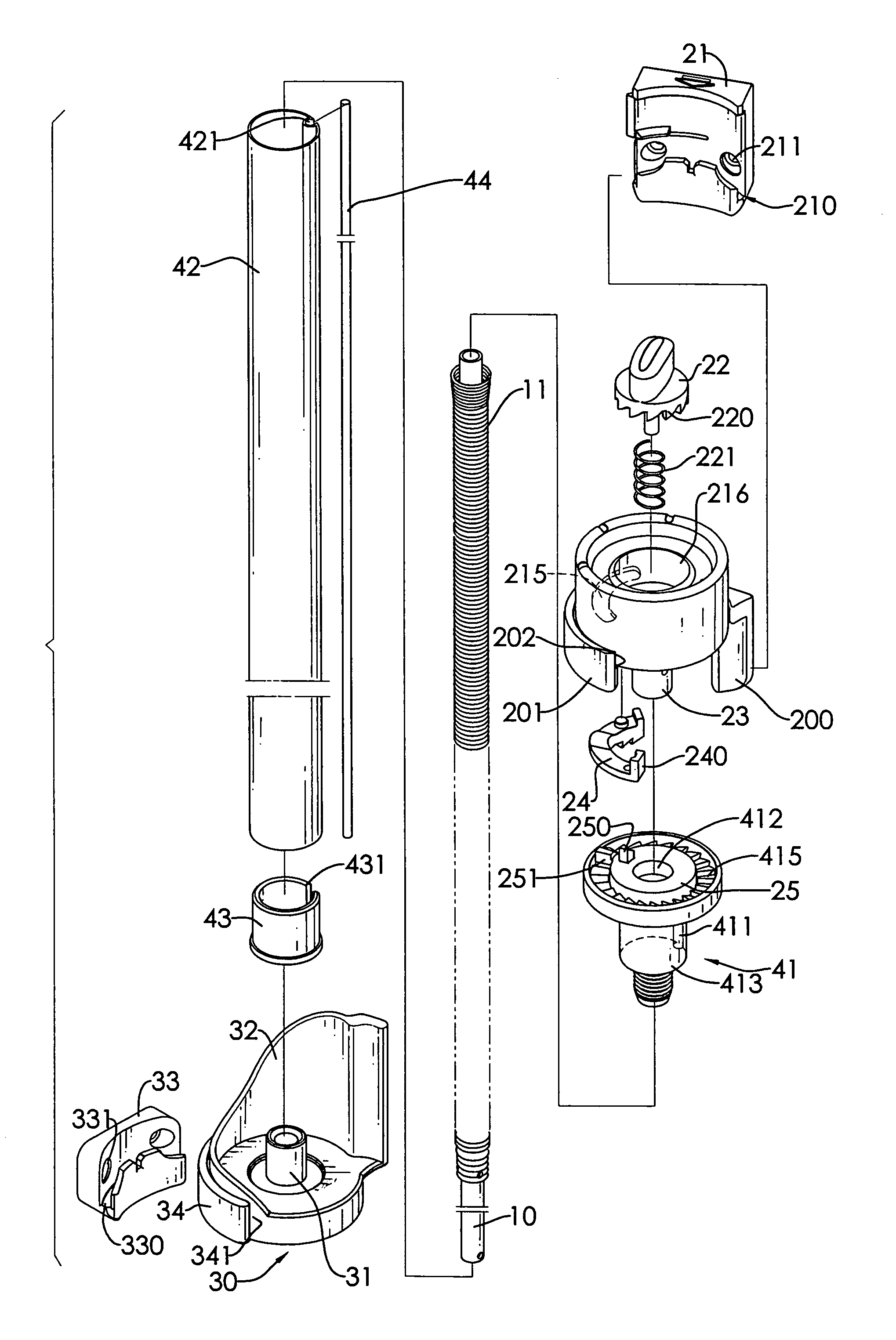
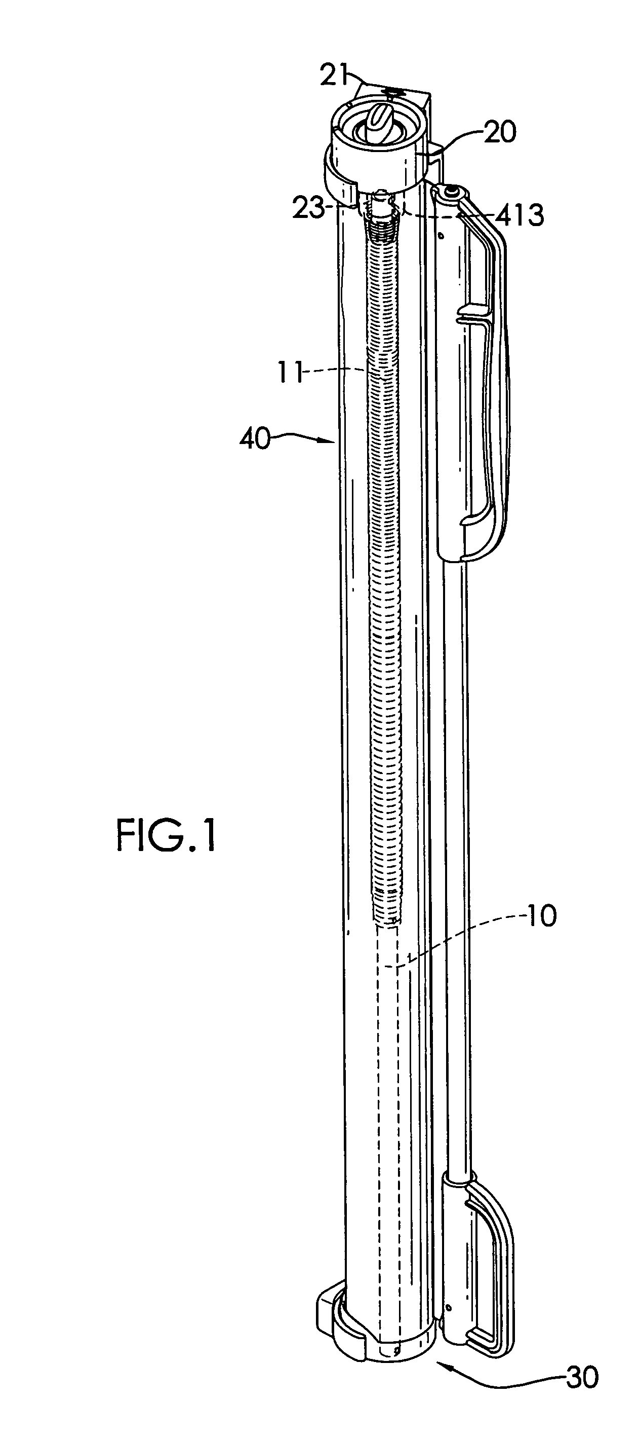
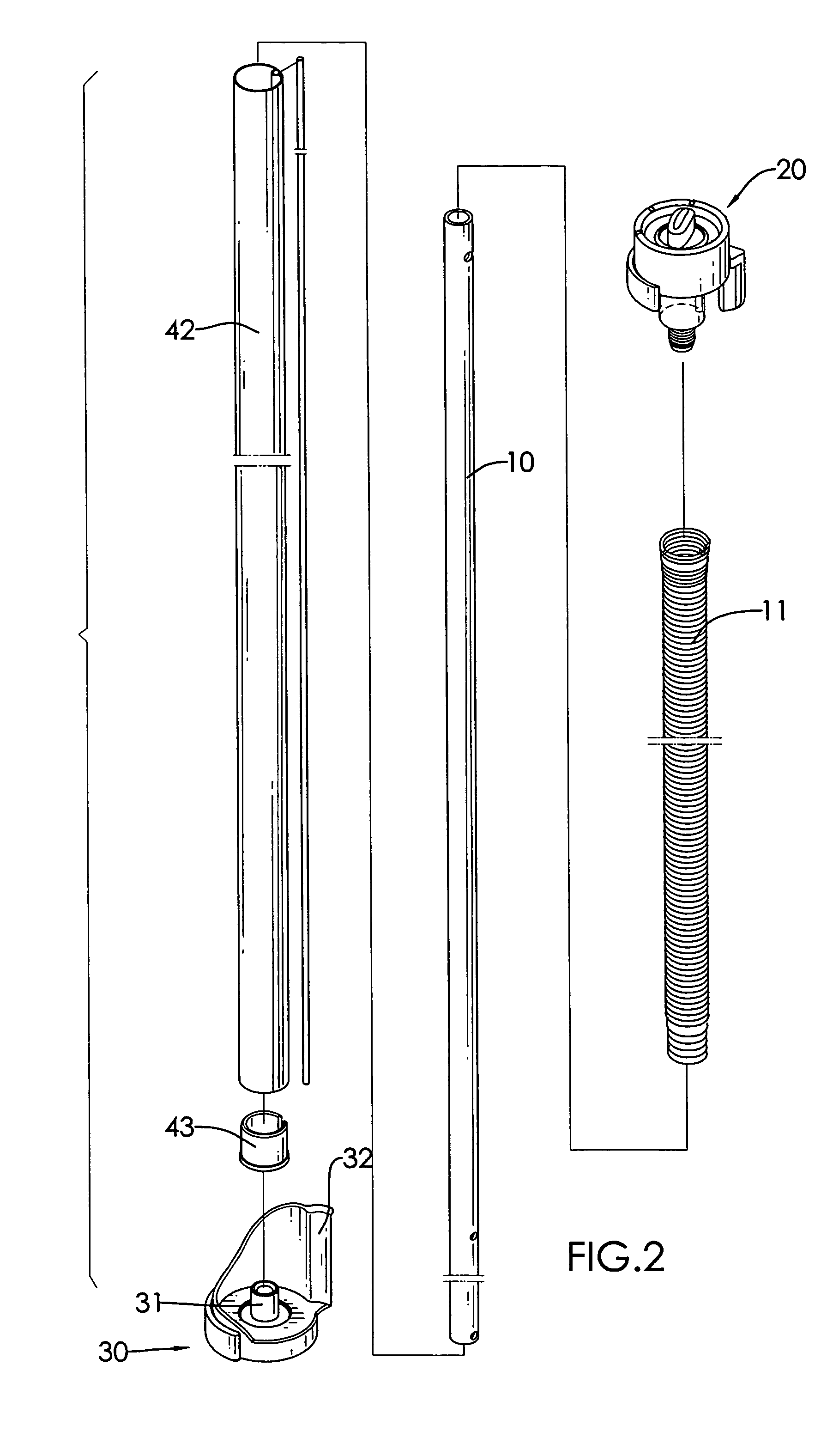
"The present invention provides a roll-up barrier that solves problems of conventional roll-up barriers. The barrier has a base, end cap, drive shaft, rolling assembly, resilient element, and flexible barrier. The end cap has an arresting mechanism and the rolling assembly has a rolling tube and rolling bushing with one-way arresting teeth. The resilient element provides a rotating reposition force and the flexible barrier is mounted retractably around the rolling tube. The invention prevents the flexible barrier from retracting when not in use and allows for easy reconnection to a stationary object. The technical effects of the invention are improved safety and convenience."

Problems solved by technology

During retraction of the flexible barrier, retracting force of the moving flexible barrier may hurt the infant or the pet.
Additionally, to pull out the flexible barrier to reconnect the distal end thereof to the hook on the adjacent stationary is inconvenient.

Method used


Image

  • Roll-up barrier
  • Roll-up barrier
  • Roll-up barrier

Examples


first embodiment

[0043]With further reference to FIG. 11, in the actuator (25), the actuator (25) further has an annular flange (254). The annular flange (254) is formed on and protrudes down from the outer edge of the actuator (25), is mounted around the connecting ring (412) and has a diameter slightly larger than that of the connecting ring (412) to slightly contact with the connecting ring. Thus, friction between the annular flange (254) and the connecting ring (412) can slightly rotate the actuator (25) when the rolling bushing (41) rotates.

second embodiment

[0044]With further reference to FIG. 12, in the actuator (25′), the actuator (25′) further has an annular flange (254′) and a clipping slot (253). The annular flange (254′) is formed on and protrudes down from the outer edge of the actuator (25) and is mounted around the connecting ring (412). The clipping slot (253) is formed radially through the annular flange (254′) and communicates with the central hole in the actuator (25′). Thus, the annular flange (254′) has a slight resilience to slightly contact with the connecting ring (412) such that friction between the annular flange (254′) and the connecting ring (412) can slightly rotate the actuator (25′) when the rolling bushing (41) rotates.

[0045]The one-way arresting teeth (415) are formed on the top of the rolling bushing (41) around the actuator (25, 25′) and corresponds to and selectively engage the one-way toothed section (242). When the arrestor (24) is lifted up by the actuating lug (251) of the actuator (25, 25′), the one-w...


PUM


Abstract

A roll-up barrier has a base, an end cap, a drive shaft connected between the base and the end cap, a rolling assembly, a resilient element and a flexible barrier. The end cap has an arresting mechanism having a control button and an arrestor. The rolling assembly is mounted rotatably around the drive shaft and has a rolling bushing. The rolling bushing has an actuator and multiple one-way arresting teeth. The resilient element provides a reposition force for rolling back the rolling assembly. The flexible barrier is mounted retractably around the rolling assembly. When the control button is pressed and rotated, the actuator detaches the arrestor from the arresting teeth to allow rotation of the rolling assembly. When the control button is released, the arrestor engages the arresting teeth to prevent the rolling assembly from rotation so the flexible barrier can be pulled out and held at a desired length.

Description

BACKGROUND OF THE INVENTION[0001]1. Field of the Invention[0002]The present invention relates to a roll-up barrier, and more particular to a roll-up barrier that has a flexible barrier can be pulled out and held at a desired length and can be conveniently retracted.[0003]2. Description of Related Art[0004]A safe zone in which an infant or a pet can play to limit access to hazardous areas is defined with a temporary barrier or gate mounted between two walls or in a doorway.[0005]For make storage convenient, various kinds of roll-up barriers have been developed. Generally, a conventional roll-up barrier has a rolling tube, a flexible barrier and a resilient element. The rolling tube is positioned on a stationary, e.g. a wall, a doorjamb or the like. The flexible barrier is mounted around the rolling tube and has a proximal edge and a distal edge. The proximal edge of the flexible barrier is mounted securely on the rolling tube. The distal edge of the flexible barrier can be pulled out...

Claims


Application Information

Patent Timeline
Patent Type & Authority Patents(United States)
IPC IPC(8): A47H1/00
CPCE01F13/028E06B9/80E06B2009/002E06B9/08
Inventor CHENG, SHU-CHEN
Owner CHENG SHU CHEN
Learn More