
Piston-cylinder device with position sensing means

a technology of position sensing and piston cylinder, which is applied in the direction of machines/engines, instruments, and converting sensor output using wave/particle radiation. it can solve the problems of limiting the operation control possibilities of the piston, difficult to obtain a quick and easy setting of the sensors in the cylinder barrel, and a lot of tim

Inactive Publication Date: 2008-10-21
PARKER HANNIFIN AB
View PDF8 Cites 16 Cited by
  • Summary
  • Abstract
  • Description
  • Claims
  • Application Information

AI Technical Summary

Problems solved by technology

A problem concerned with this known technique is the difficulty to obtain a quick and easy setting of the sensors in the cylinder barrel.
These sensors have to be moved individually and locked in their intended positions by manual operations, which is rather tricky and time consuming.
Another problem is that the number of indicated positions is limited to a few points, which is limiting to the piston operation control possibilities.
A further problem concerned with this known technique is to accomplish a compact piston-cylinder device where the position sensing means, including signal treating electronic components, do not add to the outer dimensions of the device but are confined within the outer dimensions of a standard type piston-cylinder device and safely protected from inter alia mechanical damage.
This is, however, a rather awkward location of the transducer, because it not only requires an expensive specially designed piston / piston rod and cylinder end wall but the transducer is difficult to get to in case of maintenance and replacement.
A problem arising at piston-cylinder device applications is to find a way to locate the transducer without complicating the cylinder design compared to the above related common technique.
This means not only that a specially designed cylinder barrel with a drilled extra bore for the sensor has to be used, but also that the arrangement of the electronic evaluating device adds to the length of the cylinder.

Method used


Image

  • Piston-cylinder device with position sensing means
  • Piston-cylinder device with position sensing means

Examples


Embodiment Construction

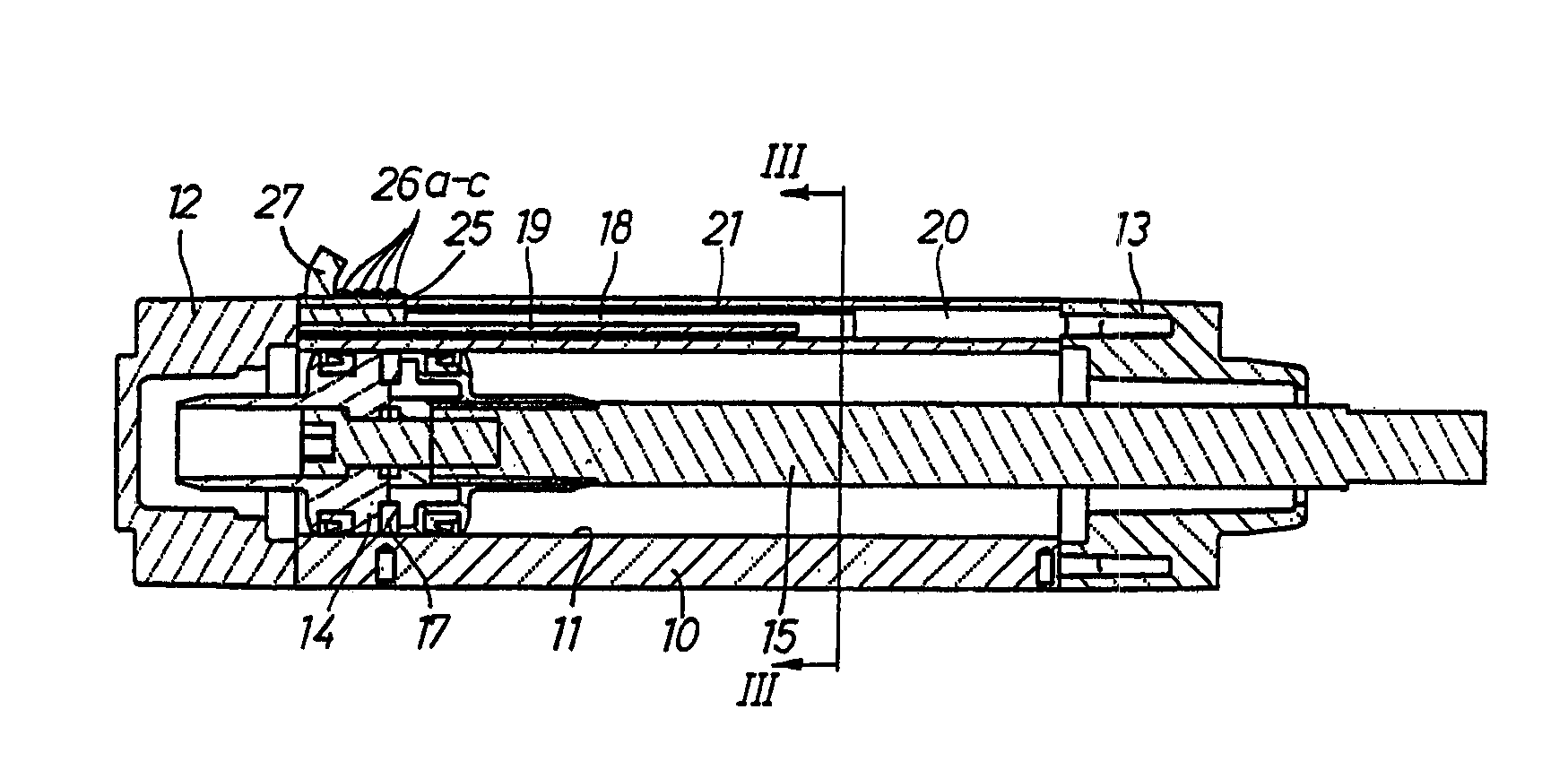
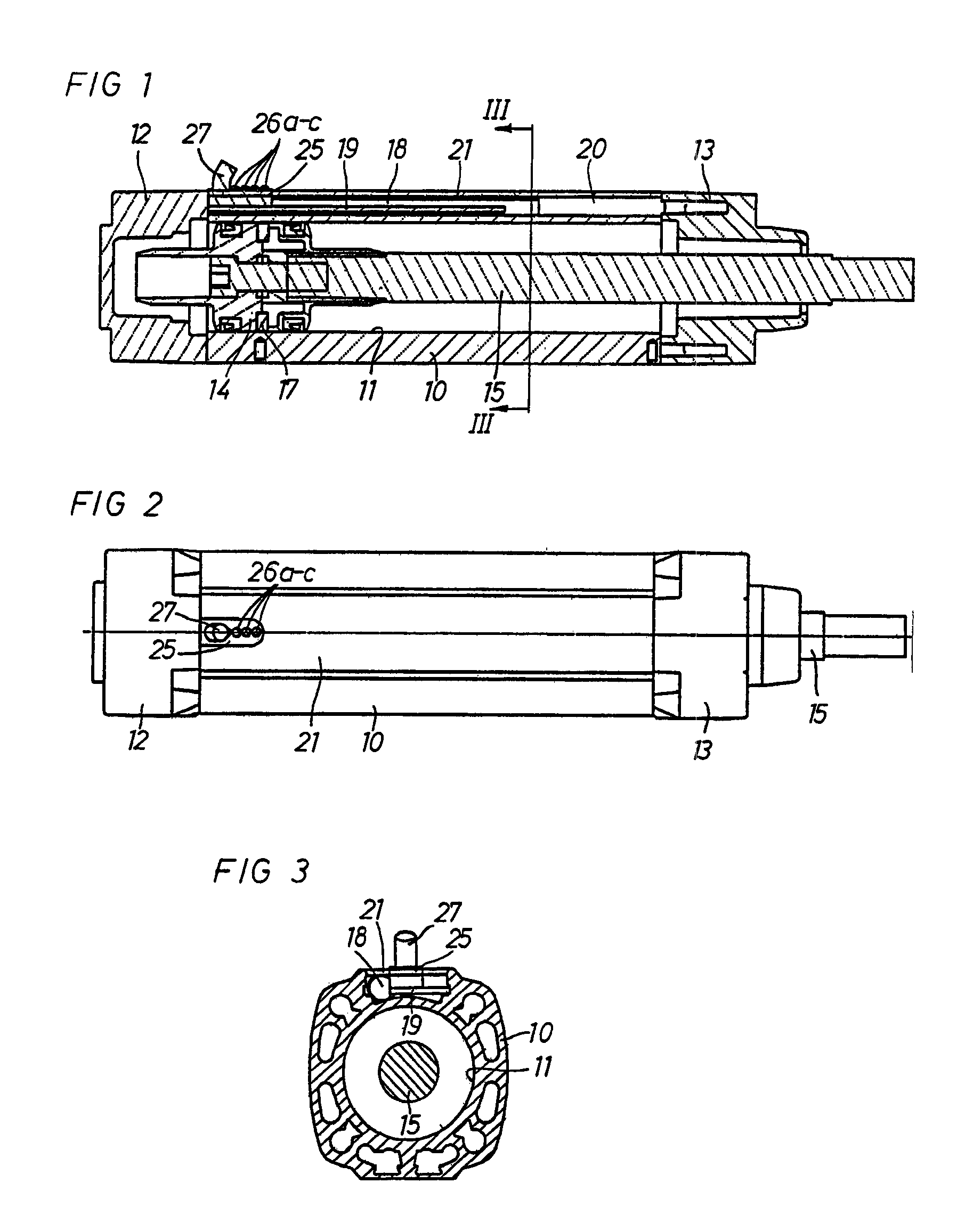
[0012]The piston-cylinder device illustrated in the drawings comprises a cylinder barrel 10 with a cylinder bore 11 and two opposite end walls 12 and 13, a piston 14 movably guided in the cylinder bore 11 and a piston rod 15 extending out of the cylinder barrel 10 via an opening in one of the end walls 12. The cylinder barrel 10 is of a standard type including an extruded aluminium alloy body with an outer elongate cavity or channel 20, which is formed at the extrusion process. This means that no advanced extra machining of the barrel 10 is necessary. The cylinder barrel 10 as well as the complete piston-cylinder device is dimensioned to meet the international standard specifications of ISO and VDM A.

[0013]In a common way, the cylinder barrel 10 is provided with non-illustrated connections for communication of a pressure medium to and from the cylinder bore 11 as well as passages for ducting motive pressure medium to and from the ends of the cylinder bore 11 for accomplishing moveme...


PUM


Abstract

A pressure activated piston-cylinder device includes a cylinder barrel with a cylinder bore, a piston with a piston rod movably guided in the cylinder bore, and a piston position sensing and indicating device. The piston position sensing and indicating device includes a magnetic activating element carried on the piston and an elongate electronic contact free transducer mounted on the cylinder barrel. The cylinder barrel includes a standard type extruded aluminum alloy barrel with an outer channel which extends in an offset parallel disposition relative to the cylinder bore, and a circuit board with electronic components connected to the transducer. The transducer as well as the circuit board are located in the groove in the cylinder barrel.

Description

FIELD OF THE INVENTION[0001]The invention relates to a pressure medium activated piston-cylinder device with a piston position indicating device which comprises a magnetic activating element on the piston and a sensor means supported on the cylinder barrel.DESCRIPTION OF RELATED ART[0002]According to a common technique, indication of piston positions in a cylinder bore is accomplished by a device comprising a magnetic activating element mounted on the piston and one or more single-point sensors adjustably mounted on the cylinder barrel. A problem concerned with this known technique is the difficulty to obtain a quick and easy setting of the sensors in the cylinder barrel. These sensors have to be moved individually and locked in their intended positions by manual operations, which is rather tricky and time consuming. Another problem is that the number of indicated positions is limited to a few points, which is limiting to the piston operation control possibilities.[0003]A further pr...

Claims


Application Information

Patent Timeline
Patent Type & Authority Patents(United States)
IPC IPC(8): F01B31/12F15B15/28G01D5/48G01D11/30
CPCF15B15/2892F15B15/2861G01D11/30G01D5/485
Inventor ANDERSSON, BO AKEJOHANSSON, PAR GUNNAR JOHAN
Owner PARKER HANNIFIN AB
Learn More