
Video processing methods

a video processing and video technology, applied in the field of data processing methods, can solve the problems of time-consuming, difficult to accurately locate the frame using the default time scale value, and excessive time consumption when searching for the desired fram

Inactive Publication Date: 2008-10-14
8324450 DELAWARE +1
View PDF26 Cites 35 Cited by
  • Summary
  • Abstract
  • Description
  • Claims
  • Application Information

AI Technical Summary

Benefits of technology

"The patent describes a video editing interface and a method for searching and moving frames in a video. The interface has three sub-regions: a first sub-region, a second sub-region, and a third sub-region. The first sub-region has a smaller time scale value and low-speed and medium-speed controls for scrolling forward and backward on the timeline. The second sub-region has a larger time scale value and high-speed controls for scrolling forward and backward. The third sub-region has a smaller time scale value and high-speed controls for scrolling forward and backward. The method allows for easy searching and moving of frames in the video."

Problems solved by technology

When a frame requires editing, it is difficult to accurately locate the frame using the default time scale value.
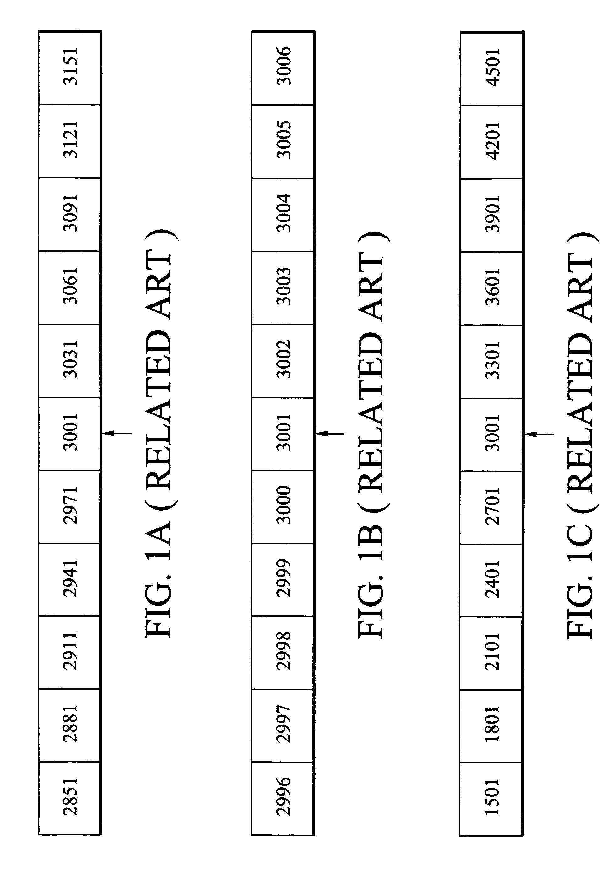
Additionally, the slider is located at the 3001st frame on the timeline, as shown in FIG. 1A, and locating the 15000th frame using the time scale value ( 1 / 30 seconds or one second) can be time-consuming.
As summarized above, conventional video editing methods force a user to repeatedly change the time scale, thus consuming excessive time when searching for a desired frame.

Method used


Image

  • Video processing methods
  • Video processing methods
  • Video processing methods

Examples


Embodiment Construction

[0021]Video processing methods and video editing interfaces thereof are provided.

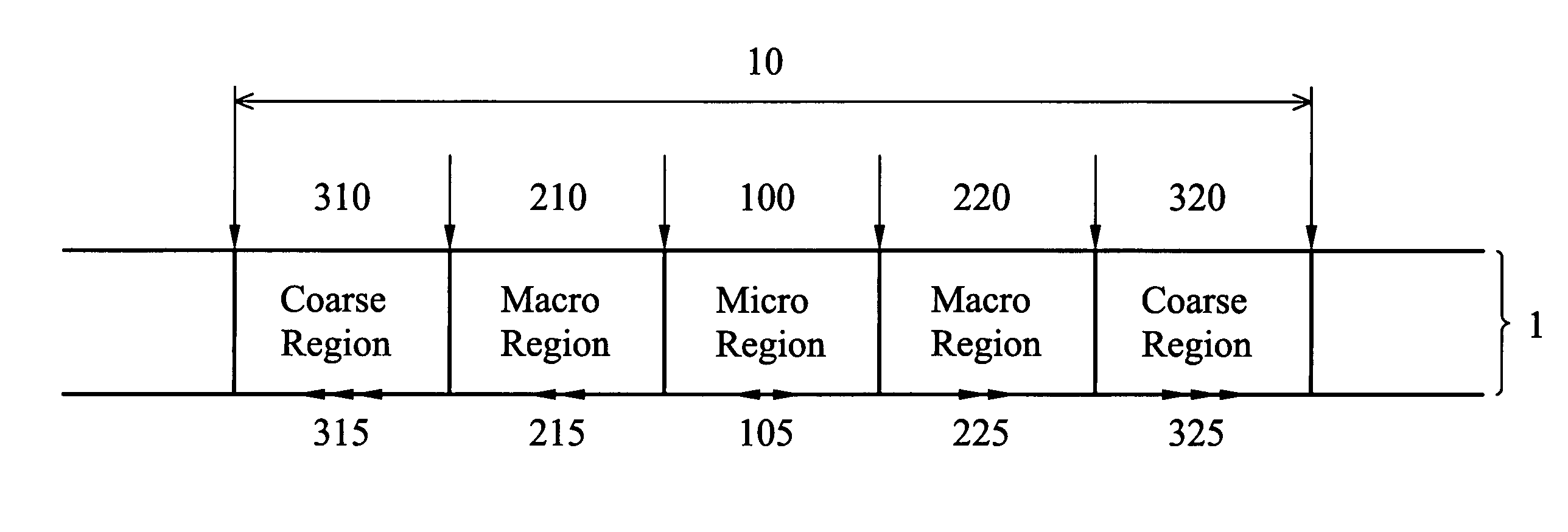
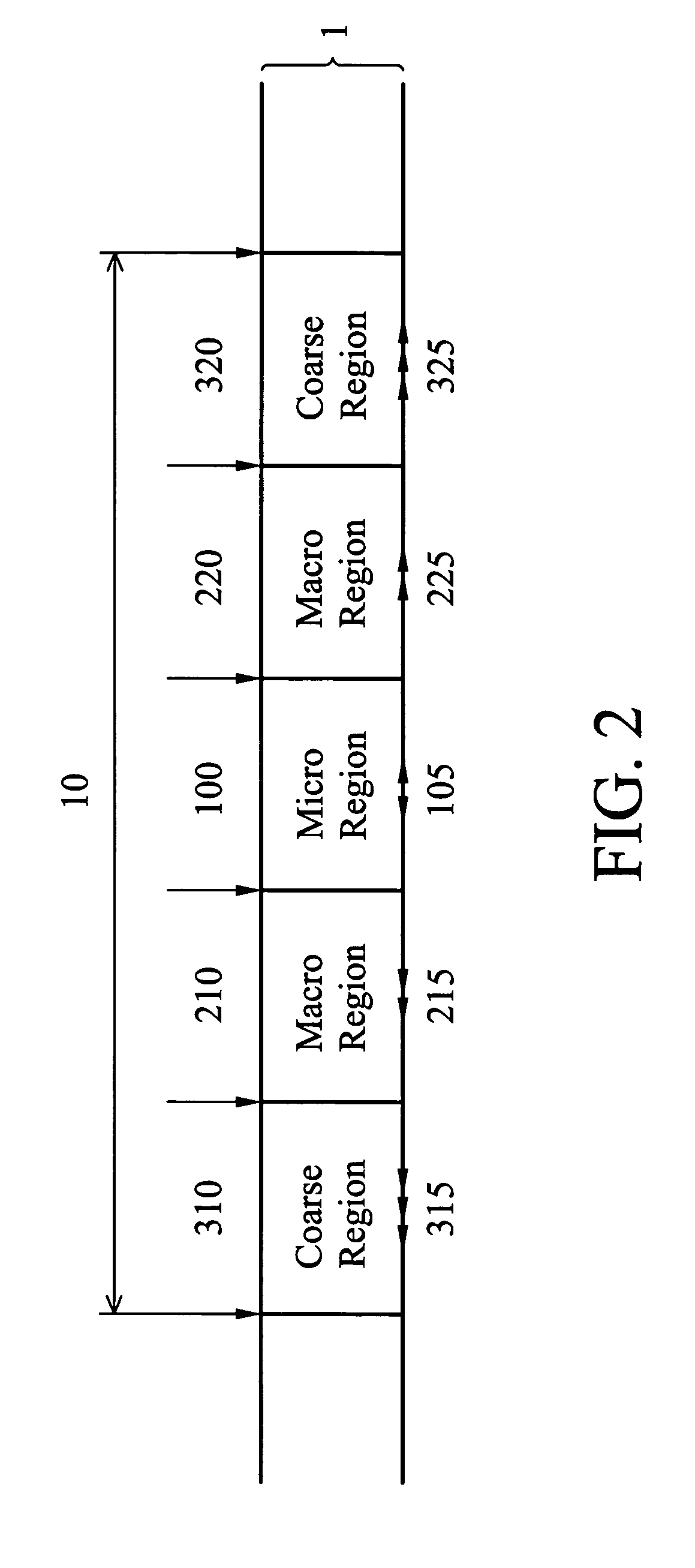
[0022]As will be described in detail hereafter, some embodiments comprise at least a video editing interface as shown in FIG. 2.

[0023]Some embodiments comprise display region 10, comprising a micro region 100, macro regions 210 and 220, and coarse regions 310 and 320, according to a timeline 1. Micro region 100 has a low-speed control 105, macro regions 210 and 220 have medium-speed controls 215 and 225 respectively, and coarse regions 310 and 320 have high-speed controls 315 and 325 respectively. A time scale value of micro region 100 is less than time scale values of macro regions 210 and 220 respectively, and the time scale values of macro regions 210 and 220 are less than the time scale values of coarse regions 310 and 320 respectively.

[0024]FIG. 3 is flowchart showing an embodiment of a video processing method. A display region, as shown in FIG. 2, comprising a first sub-region, two second sub-regi...


PUM

PropertyMeasurementUnit
timeaaaaaaaaaa
time scaleaaaaaaaaaa

Abstract

A video processing method. A display region is provided according to a timeline, comprising at least one first sub-region with higher time resolution and one second sub-region with lower time resolution. A time scale value of the first sub-region is smaller than that of the second sub-region, and the first and second sub-regions have low-speed and medium-speed controls for scrolling forward and backward respectively. When a desired frame is located in the first sub-region, the low-speed or medium-speed control is scrolled to forward or backward on the timeline according to an operating command to locate the desired frame. When the desired frame is located in the second sub-region, the low-speed or medium-speed control is scrolled to forward or backward on the timeline according to an operating command to move the desired frame to the first sub-region.

Description

[0001]This Non-provisional application claims priority under 35 U.S.C. § 119(a) on Patent Application No(s). 2004-104583 filed in Japan on Mar. 31, 2004, the entire contents of which are hereby incorporated by reference.BACKGROUND OF THE INVENTION[0002]The invention relates data processing methods, and in particular to video processing methods.[0003]In some conventional video editing software applications, a slider is dragged along a timeline to move a desired frame to a display region for video processing using editing tools. Time scale values applied in current video editing tools are fixed, such that when the slider moves on the timeline, it travels one unit per movement with shifting a predetermined number of frames. Thus, a desired frame can be located by repeatedly changing the time scale value.[0004]A film, for example, shot at a rate of thirty frames per second with duration of one hour, comprises 108000 frames. As shown in FIG. 1, suppose a default time scale value is one s...

Claims


Application Information

Patent Timeline
Patent Type & Authority Patents(United States)
IPC IPC(8): G06F3/00H04N5/91G06F17/21G11B27/00G11B27/02G11B27/34H04N5/253
CPCG11B27/005G11B27/34G11B27/02
Inventor CHEN, YI-KAI
Owner 8324450 DELAWARE
Learn More