
Fly by wire static longitudinal stability compensator system

a compensator system and flight control technology, applied in process and machine control, instruments, navigation instruments, etc., can solve the problems of small engagement errors, unsatisfactory aircraft response, and much benign overall maneuver

Inactive Publication Date: 2008-10-07
SIKORSKY AIRCRAFT CORP
View PDF5 Cites 12 Cited by
  • Summary
  • Abstract
  • Description
  • Claims
  • Application Information

AI Technical Summary

Benefits of technology

The present invention is a flight control system that provides an unobtrusive airspeed hold function that reacts to pilot control inputs and the measured states of the aircraft to engage and disengage smoothly without any explicit mode selection by the pilot. This mode is only provided when the Full Primary Flight Control System (PFCS) mode is available, i.e. there are no losses of sensor data, and the pilot has not engaged any other automatic or Flight Director stabilization modes. The system allows the pilot to either fly close to a desired airspeed and let SLS engage, or he can trim the aircraft in an accelerating / decelerating maneuver and just wait for the SLS to capture a speed when longitudinal acceleration is small. The system will disengage if any of the following occur: the SLS enable logic goes FALSE, the absolute pilot / copilot longitudinal stick command is out of detent for more than 0.5 seconds or exceeds the absolute lateral stick command up to a value of 10%, the absolute shaped yaw command is greater than 10%, the longitudinal beeper is activated, the longitudinal cyclic rotor command is on its limit, or the PFCS—CLAWS—IC—LOGIC is TRUE. The invention provides an FBW static longitudinal stability system that provides an unobtrusive airspeed hold function that reacts to pilot control inputs and the measured states of the aircraft to engage smoothly without any explicit mode selection by the pilot.

Problems solved by technology

The use of the adaptive synchronizer results in a smooth transition into airspeed hold, only a small error between desired and actual airspeed and no over-shoot of the steady-state airspeed reference.
The result can be an unsatisfactory aircraft response when the mode engages.
Since there is no intent to drive the aircraft back to the original engagement airspeed, the overall maneuver is much more benign and engagement errors are small.

Method used


Image

  • Fly by wire static longitudinal stability compensator system
  • Fly by wire static longitudinal stability compensator system
  • Fly by wire static longitudinal stability compensator system

Examples


Embodiment Construction

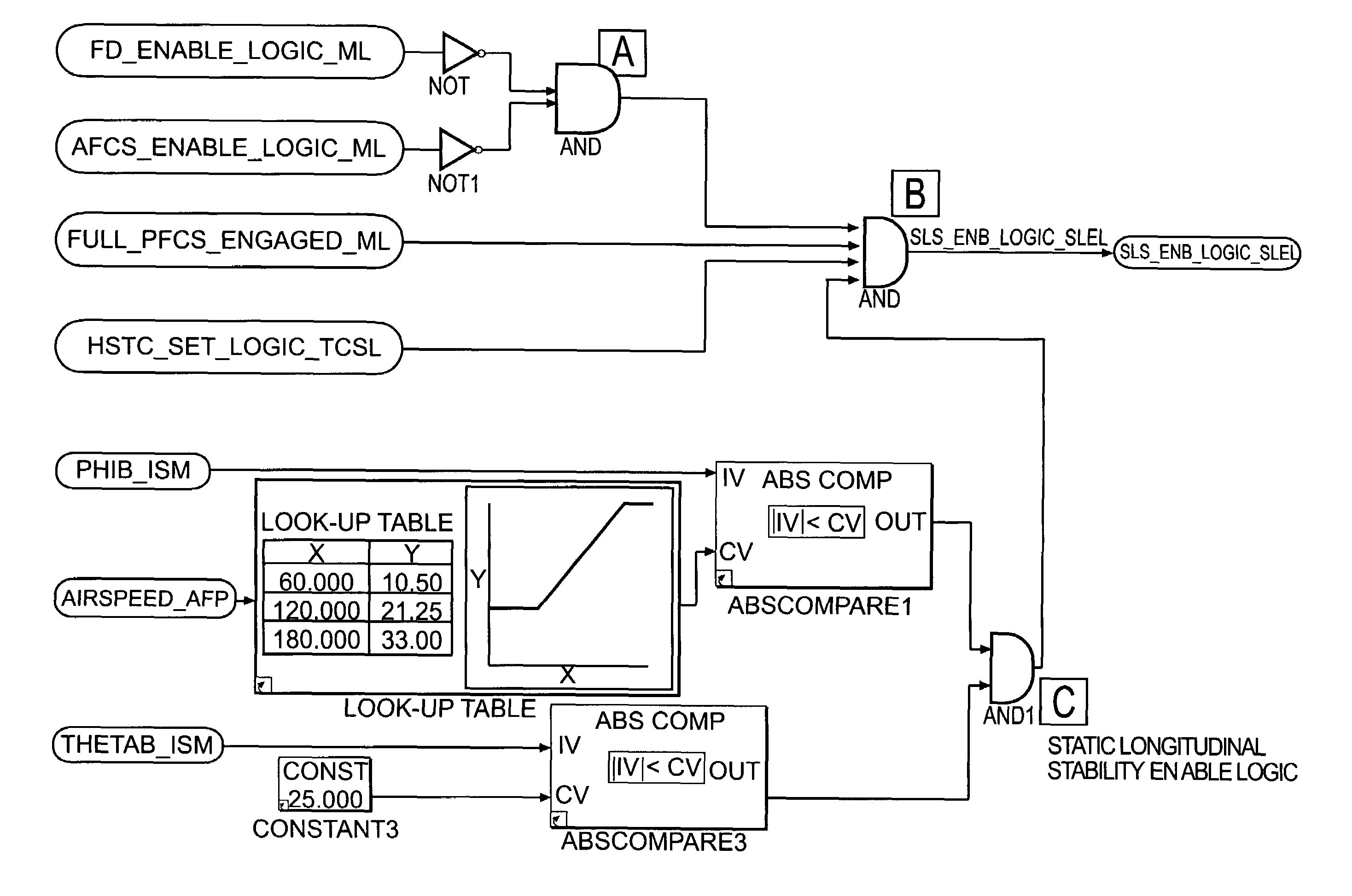
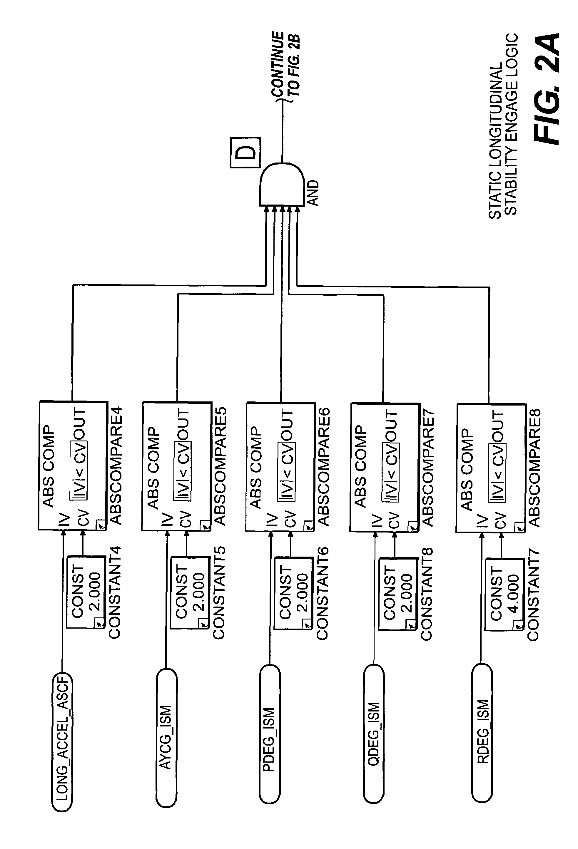
[0018]The Static Longitudinal Stability (SLS) Compensation System designed according to the present invention is divided into three sections: enable logic (FIG. 1), engage logic (FIGS. 2A and 2B), and compensation shaping (FIGS. 3A and 3B).

[0019]Determining the trim condition necessary to enter airspeed hold requires monitoring aircraft states and interpreting pilot inputs. The flight regime for which this is applicable includes high-speed steady level flight (V>50 knots), coordinated turns of reasonable aggressiveness, and gentle ascents and descents. Linear accelerations, angular rates, and bank angle are used to determine aircraft trim. Additional parameters can be monitored to tailor mode engagement requirements for a given control strategy. Pilot interaction with the system also dictates mode transition. Certain pilot input will cause the mode to disengage. Pilot stick or beeper interaction automatically switches the control system to the desired Rate Command / Attitude Hold cont...


PUM


Abstract

A static longitudinal stability (SLS) system provides an unobtrusive airspeed hold function that reacts to the pilot control inputs into the flight control system and the measured states of the aircraft to engage and disengage smoothly without any explicit mode selection by the pilot. The SLS engages airspeed hold when the aircraft is close to trimmed, non-accelerating state. This logic allows the pilot to either fly close to a desired airspeed and let SLS engage, or trim the aircraft in an accelerating / decelerating maneuver and just wait for the SLS to capture a speed when longitudinal acceleration is small. The SLS is not dependant on the pilot specifically selecting this mode, but rather engages and disengages in response to flight control system status and how the aircraft is being maneuvered.

Description

BACKGROUND OF THE INVENTION[0001]The present invention relates to a fly-by-wire flight control system, and more particularly to an airspeed hold system.[0002]Fly By Wire (FBW) flight control systems are emerging as state of the art in control of rotary-wing aircraft. FBW permits a wide range of improvements that contribute to pilot workload reductions. Although significant benefits are realized with FBW systems, advanced system hardware may alter the pilot-vehicle interface in such a way that civil certification requirements may not be met. Special provisions must then be made in the control system to meet these requirements, which may compromise performance benefits of FBW.[0003]The static position of the longitudinal cyclic flight controls which control aircraft pitch altitude, change as a function of aircraft flight conditions. The pilot typically retrims the forces felt on the stick each time the flight conditions (speed of forward travel, climb / decent angle) are changed. Such r...

Claims


Application Information

Patent Timeline
Patent Type & Authority Patents(United States)
IPC IPC(8): B64C27/04B64C37/00G06F19/00
CPCG05D1/0202G05D1/0808
Inventor FANCIULLO, TODD M.GOLD, PHILLIP J.
Owner SIKORSKY AIRCRAFT CORP
Learn More