
Signal conditioning circuit

a signal processing circuit and signal technology, applied in the direction of brightness and chrominance signal processing circuits, television systems, pulse techniques, etc., to achieve the effect of reducing interference on lines, reducing interference, and reducing interferen

Active Publication Date: 2008-10-07
APPLE INC
View PDF5 Cites 3 Cited by
  • Summary
  • Abstract
  • Description
  • Claims
  • Application Information

AI Technical Summary

Benefits of technology

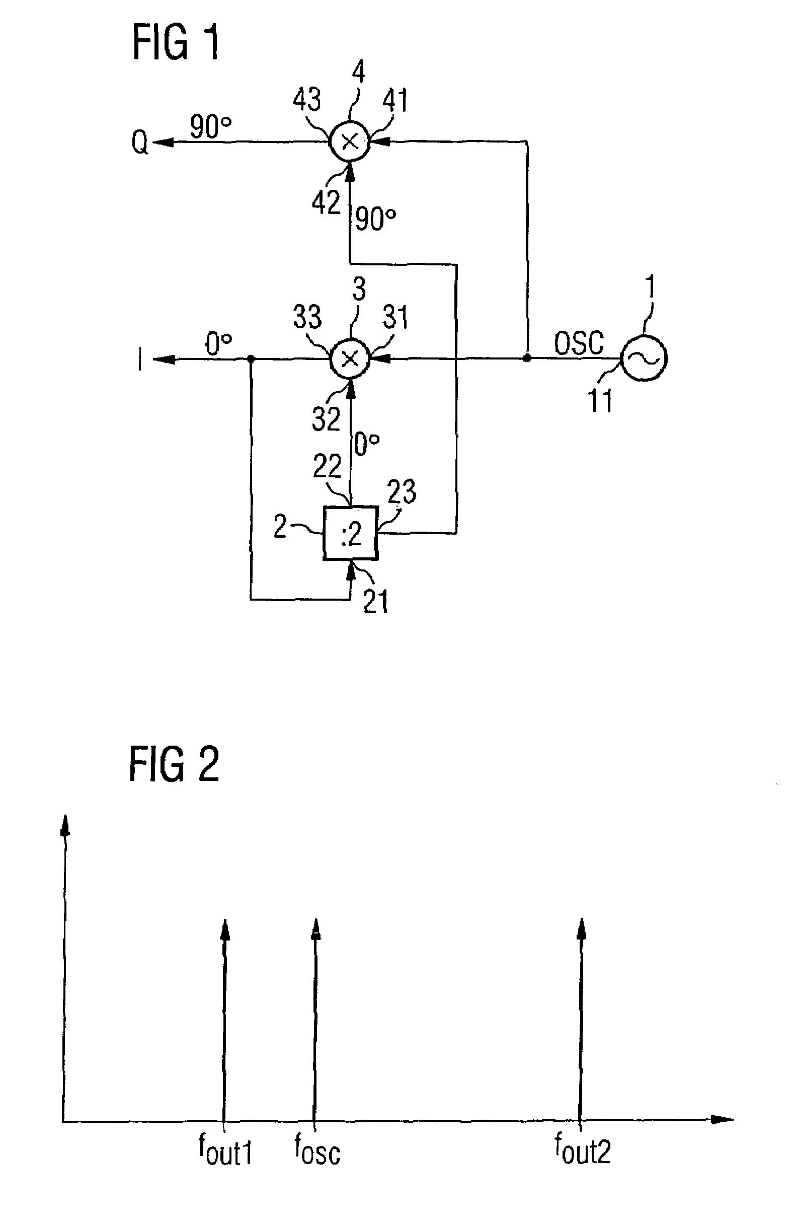
[0010]According to one or more aspects of the present invention, a signal conditioning circuit is provided that is operative to produce a complex signal having an in-phase component and a quadrature component, with the effect of the oscillator signal on the output being lessened.
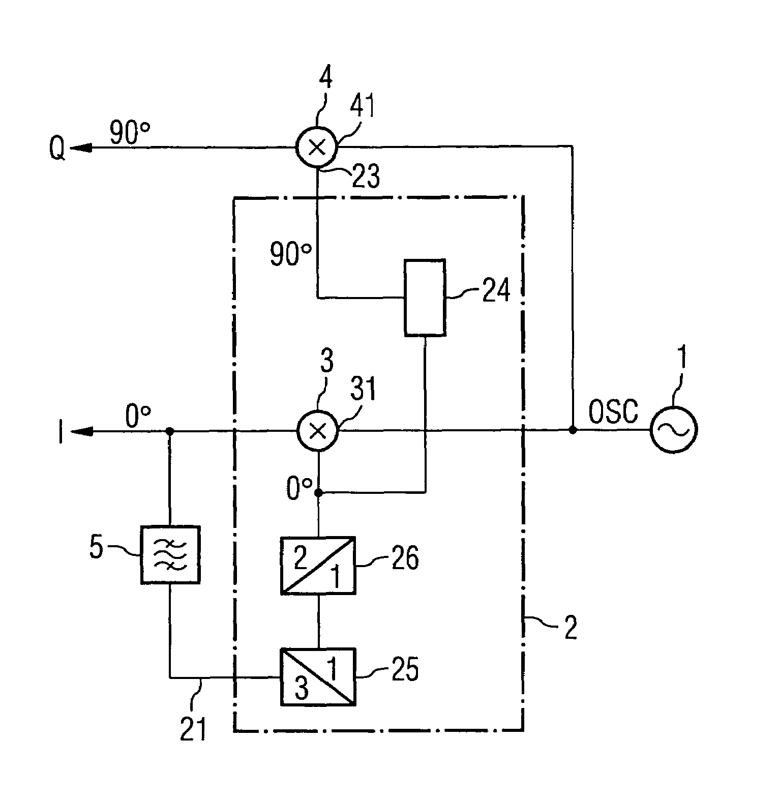
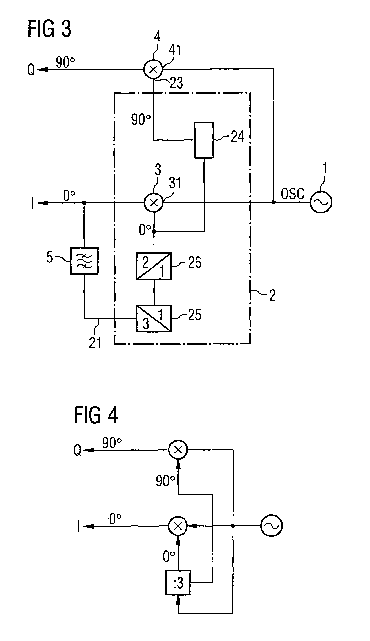
[0012]The signal conditioning circuit facilitates an improved production of a complex output signal having an in-phase component and the quadrature component. The frequency divider arrangement provides two signals which are orthogonal to one another and are used as input signals for the frequency conversion devices. The two output signals from the signal conditioning circuit are therefore orthogonal to one another as well. Feedback considerably improves the phase accuracy of the signals produced. At the same time, feedback facilitates suppression of undesirable components in the output signal and, in particular, decouples the oscillator's input signal from the output signal. Feedback results in the output signal from the conversion device having the phase relationship of the input signal.
[0014]Unlike conventional signal conditioning circuits, the circuit according to one or more aspects of the present invention is designed for difference signal processing. Interference on lines is thus reduced, in particular. In a refinement such as this, the frequency divider circuit may likewise be implemented in a particularly simple manner using a flip-flop circuit. In one particularly preferred refinement of the invention, the frequency divider circuit is in the form of a master-slave D flip-flop. This has the advantage that it oscillates freely which excites the inventive oscillator arrangement on its own. The circuit is excited, with the aid of feedback, at the ideal frequency and thus reliably starts to oscillate. The flip-flop is designed so that undesirable spectral components in the output signal are additionally suppressed by the flip-flop's greater attenuation or poorer resonant response.
[0015]In one example, the master-slave D flip-flop is designed for frequency division by even division ratios. As such, the flip-flop produces, in a simple manner, two output signals which have a phase shift of 90 degrees with respect to one another. This advantageously mitigates variations due to process fluctuations, thus enhancing production quality. The signals provided by the master-slave D flip-flop may be fed directly to the respective second input of the frequency conversion devices.
[0016]In another example, a filter device is provided in the feedback path between the signal input of the frequency divider circuit and the signal output of the first conversion device. The filter device suppresses undesirable spectral components in the output signal, so that signals at undesired frequencies are not fed to the frequency divider circuit. This considerably improves the transient response.

Problems solved by technology

Feedback results in the output signal from the conversion device having the phase relationship of the input signal.

Method used


Image

  • Signal conditioning circuit
  • Signal conditioning circuit
  • Signal conditioning circuit

Examples


Embodiment Construction

[0023]The present invention pertains to a signal conditioning circuit. One or more aspects of the present invention will now be described with reference to drawing figures, wherein like reference numerals are used to refer to like elements throughout. It should be understood that the drawing figures and following descriptions are merely illustrative and that they should not be taken in a limiting sense. In the following description, for purposes of explanation, numerous specific details are set forth in order to provide a thorough understanding of the present invention. It will be evident to one skilled in the art, however, that the present invention may be practiced without these specific details. Thus, it will be appreciated that variations of the illustrated systems and methods apart from those illustrated and described herein may exist and that such variations are deemed as falling within the scope of the present invention and the appended claims.

[0024]Turning to FIG. 1, a schem...


PUM


Abstract

A signal conditioning circuit contains an oscillator which is connected to the inputs of two mixers. The output of one mixer is coupled, so as to form a feedback path, to a frequency divider circuit whose first output is coupled to the second input of the first mixer. A second signal output of the frequency divider circuit carries a signal with a phase shift of 90 degrees with respect to the signal at the first signal output of the frequency divider circuit. The second signal is supplied to a second input of the second mixer. Feedback results in undesirable signal components in the in-phase and quadrature components being suppressed. At the same time, the in-phase and quadrature components have a fixed phase relationship with respect to one another. The signal conditioning circuit allows desired non-integer division ratios to be achieved.

Description

REFERENCE TO RELATED APPLICATIONS[0001]This application claims the benefit of the priority date of German application DE 103 44 851.9, filed on Sep. 26, 2003, the contents of which are herein incorporated by reference in their entirety.FIELD OF THE INVENTION[0002]The invention relates to a signal conditioning circuit for providing a complex output signal.BACKGROUND OF THE INVENTION[0003]Signal conditioning circuits are used, in particular, for vector modulators or for mixing received signals. The output driver may in this case be coupled to the vector modulator. A similar coupling problem also arises in the receiver path if the oscillator signal is fed back to the input of the receiver where it forms an additional, but undesirable, signal component. This additional signal component interferes with reception of the actual wanted signal. In this case, a cross-modulation product which occurs, in particular, when using a vector modulator has a particularly disruptive effect. Since, for ...

Claims


Application Information

Patent Timeline
Patent Type & Authority Patents(United States)
IPC IPC(8): H04B1/26H03B27/00H03K21/00H04N9/77H04N9/79H04N17/00
CPCH03B27/00
Inventor SEIPPEL, DIETOLFHANKE, ANDREPHAM-STABNER, DUYEN
Owner APPLE INC
Learn More