
Connecting structure of panels

a technology of interlocking structure and connecting structure, which is applied in the direction of folding cabinets, cabinets, dismountable cabinets, etc., can solve the problems of expanding storage capacity, vitally impossible for customers to change the original composition, and limited capacity of customers

Inactive Publication Date: 2008-10-07
YANG SHAOBIN
View PDF13 Cites 24 Cited by
  • Summary
  • Abstract
  • Description
  • Claims
  • Application Information

AI Technical Summary

Benefits of technology

"The invention provides a panel interlocking structure for knock down, panel based furniture that improves durability and mobility. The structure consists of interlock assemblies and connecting panels. The interlock assemblies have an interlock tube, cubical nuts, and interlock bolts, which securely engage the interlock tube and connecting panels. The connecting panels have cam locks and interlocking holes for easy assembly and disassembly. The interlock assembly can interlock up to four connecting panels in four directions. The invention allows for easy packaging and marketing of furniture in the form of assembling components."

Problems solved by technology

The problems with the typical panel based furniture include: panels can be easily damaged during assembling and disassembling, thus affecting the durability and mobility of the furniture; the composition of the furniture, including size, style and color has to be pre-determined by the manufacturer, leaving customer limited capacity to choose according their preferences; once the furniture is purchased and assembled, it is vitally impossible for customer to change the original composition, and to expand its storage capacity.

Method used


Image

  • Connecting structure of panels
  • Connecting structure of panels
  • Connecting structure of panels

Examples


embodiment 1

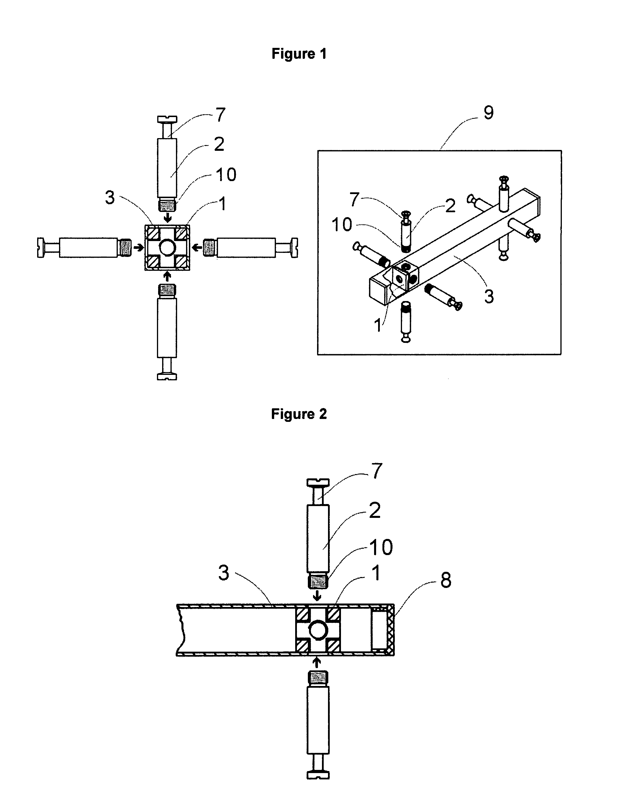
[0026]As shown in FIG. 1 to FIG. 6, the panel interlocking structure is comprising interlock assemblies 9 and connecting panels 4, in which each interlock assembly 9 consists one interlock tube 3, at least two cubical nuts 1 and at least two interlock bolts 2.

[0027]The interlock tube 3 has four lengthen rectangular faces with a continual square cross-section to its full length, and each lengthen rectangular face has at least two predrilled trans-passing holes each on a predetermined position.

[0028]Each of the cubical nut 1 has six square faces, at the center of each said square face has one predrilled thread hole, with the central line of each said predrilled thread hole intersect at the center point of the said cubical nut 1, and at least two said cubical nuts 1 are to be disposed inside the said interlock tube 3 in predetermined positions, with four predrilled thread holes on the said cubical nut 1 each opening to one corresponding trans-passing holes on one lengthen rectangular f...

embodiment 2

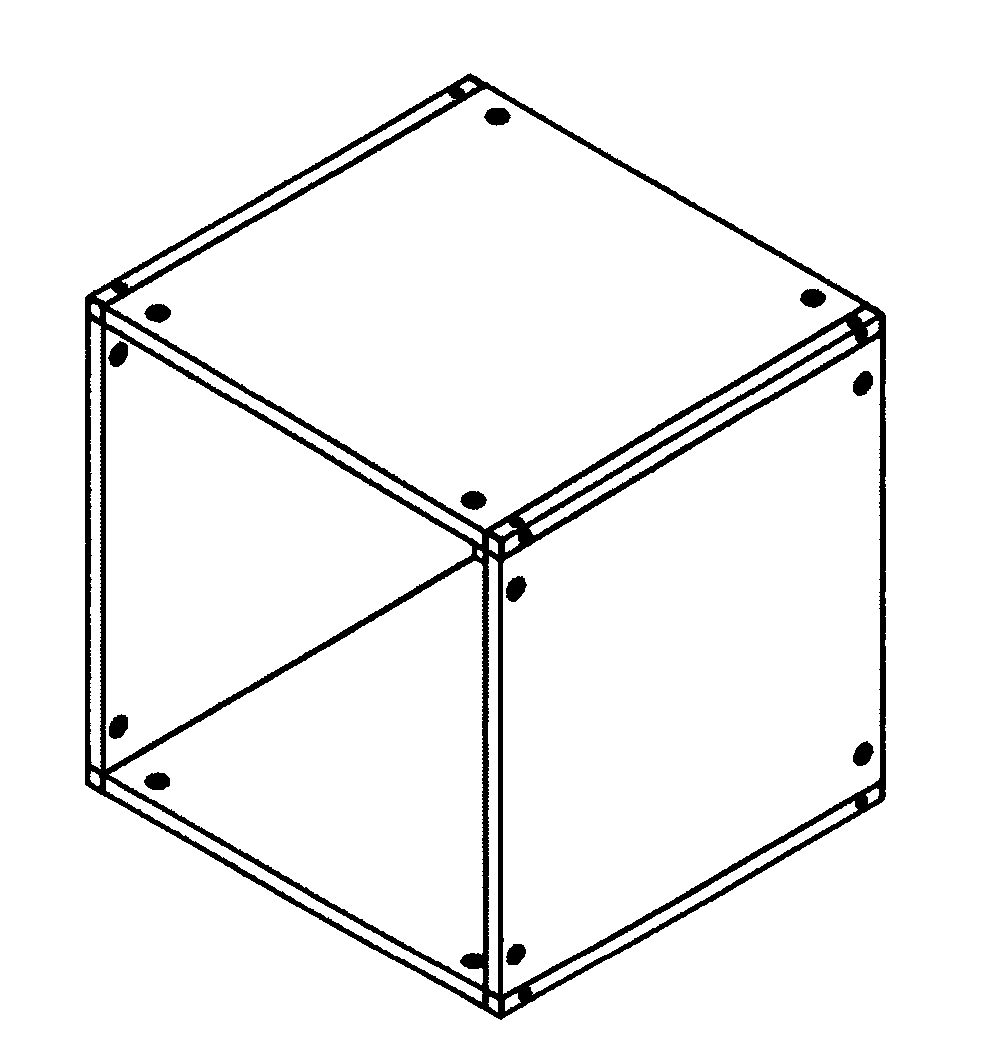
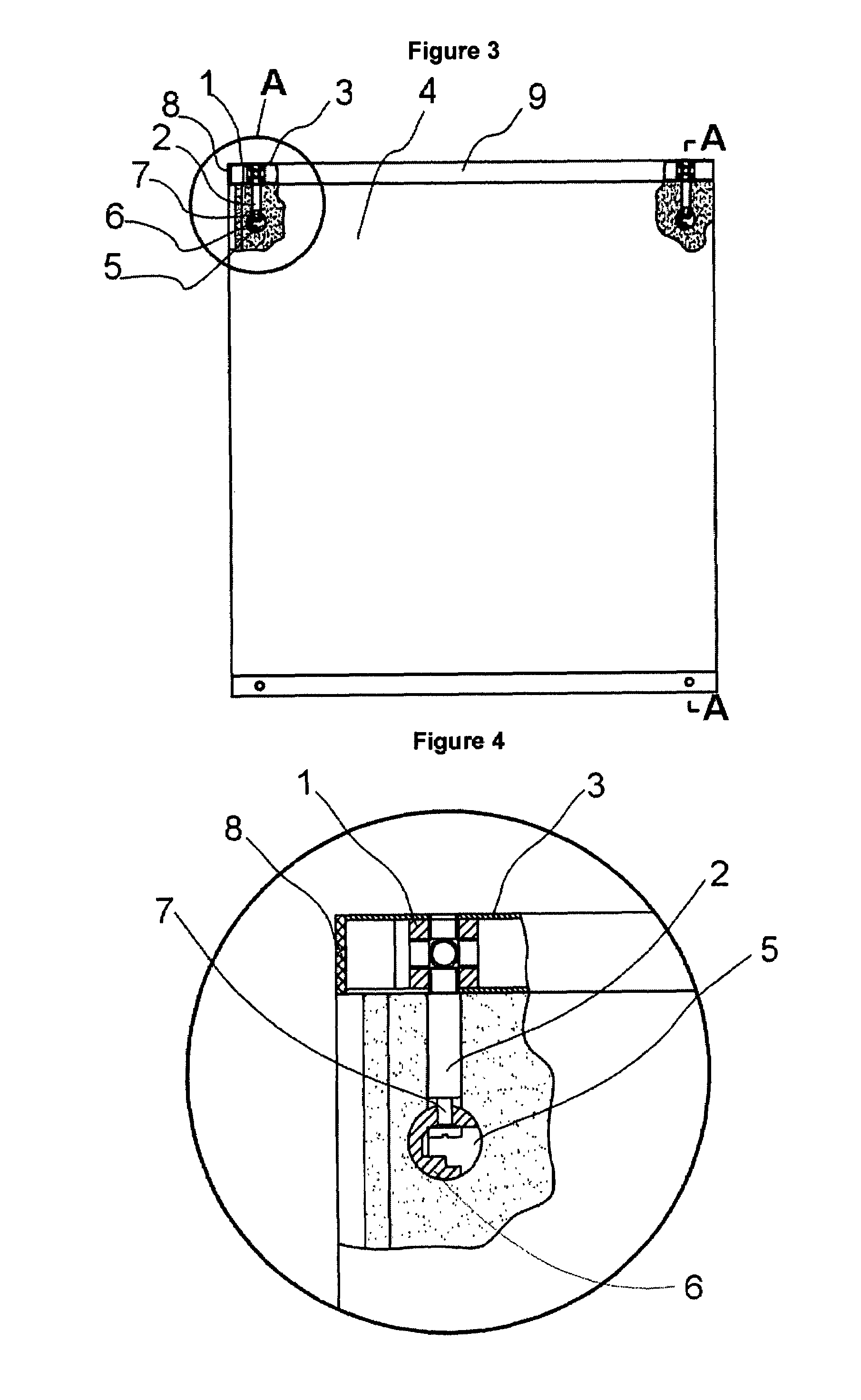
[0034]FIG. 7 and FIG. 8 further illustrate a typical knock down, panel based furniture incorporating the said panel interlocking structure. The four connecting panels 4 to be connected each has two predrilled interlocking holes on both of its connection ends; on the cam lock side of each connecting panel 4 has four predrilled dead end holes 5 each corresponding and forming a perpendicular relation to the bottom opening of the said predrilled interlocking hole and disposed with a rotatable cam lock 5 with its opening opens to the bottom opening of the predrilled interlocking hole. To make a panel connection using the said panel interlocking structure, insert the groove end 7 of the interlock bolt 2 on the interlock assembly 9 respectively into the predrilled interlocking holes on the connecting panel 4, and turn the said rotatable cam lock 5 around 90° clockwise using a screw driver, wherein the locking clasp on the said rotatable cam lock 6 thrusts engage forces to the groove end 7 ...

embodiment 3

[0035]The expandability of knock down, panel based furniture using this invention is illustrated in FIG. 9 and FIG. 10. First, add additional interlock bolts 2 onto the existing interlock assembly 9 by fastening the tread end 10 of each interlock bolt 2 to the corresponding predrilled interlocking hole on the cubical nut 1 via the trans-passing hole on the lengthen rectangular face of the respective interlock tube 3 of the interlock assembly 9 where additional connecting panel 4 is to be connected; Second, slot the additional connecting panel 4 onto the corresponding groove end of the interlock bolt 2 on the interlock assembly 9 through the predrilled interlocking hole on the respective connection end of the said connecting panel 4, and position the said groove end 7 of the interlock bolt 2 to the opening of the disposed rotatable cam lock 5 on the said additional connecting panel 4; Third, turn the said rotatable cam lock 5 around 90° clockwise using a screw driver, thus the lockin...


PUM


Abstract

A panel interlocking structure for adjacent panels of knock down, panel-based furniture, comprising interlock assemblies and connecting panels. Each interlock assembly consists one interlock tube, at least two cubical nuts and at least two interlock bolts. To form the interlock assembly, on a predetermined lengthen rectangular face of the interlock tube, via its corresponding predrilled trans-passing holes, fasten a predetermined number of the interlock bolts into the corresponding tread holes of the cubical nuts positioned inside the interlock tube, with each groove end of the interlock bolt positioned outwardly. Each connecting panel consists one cam lock side and two connection ends. Through the interlocking hole on the predetermined connection end of the connecting panel, the groove end of each interlocking bolt on the interlock assembly is inserted into the corresponding opening of the rotatable cam lock disposed in the dead end hole on the cam lock side of the connecting panel, and securely engages with the connecting panel by fastening the rotatable cam lock, thus thrusting engage forces to the groove end of each interlock bolt on the interlock assembly. All connecting panels are inter-connected via number of interlock assemblies. The invention provides improved durability, enhanced mobility, design-it-yourself capacity, as well as composition expandability for knock down, panel based furniture.

Description

BACKGROUND OF THE INVENTION[0001]1. Field of the Invention[0002]This invention relates to a panel interlocking structure for adjacent panels of knock down, panel based furniture, in particular, a panel interlocking structure providing improved durability, enhanced mobility, design-it-yourself capacity, as well as composition expandability for knock down, panel based furniture.[0003]2. Description of Prior Art[0004]Typical knock down, panel based furniture consists of different panels in a direct connection relationship, with pre-determined size, style and color. The problems with the typical panel based furniture include: panels can be easily damaged during assembling and disassembling, thus affecting the durability and mobility of the furniture; the composition of the furniture, including size, style and color has to be pre-determined by the manufacturer, leaving customer limited capacity to choose according their preferences; once the furniture is purchased and assembled, it is vi...

Claims


Application Information

Patent Timeline
Patent Type & Authority Patents(United States)
IPC IPC(8): A47B43/00A47B87/02A47B47/00F16B12/18F16B12/20
CPCA47B47/0041F16B12/2036
Inventor YANG, SHAOBIN
Owner YANG SHAOBIN
Learn More