
Interactive IR electronic white board

a technology of electronic white boards and infrared light, applied in the field of interactive infrared electronic white boards, can solve the problems of white noise, low cost of materials, and inconvenient use, and achieve the effects of low complexity, low cost, and durable surfa

Inactive Publication Date: 2008-09-30
HO WAI
View PDF3 Cites 58 Cited by
  • Summary
  • Abstract
  • Description
  • Claims
  • Application Information

AI Technical Summary

Benefits of technology

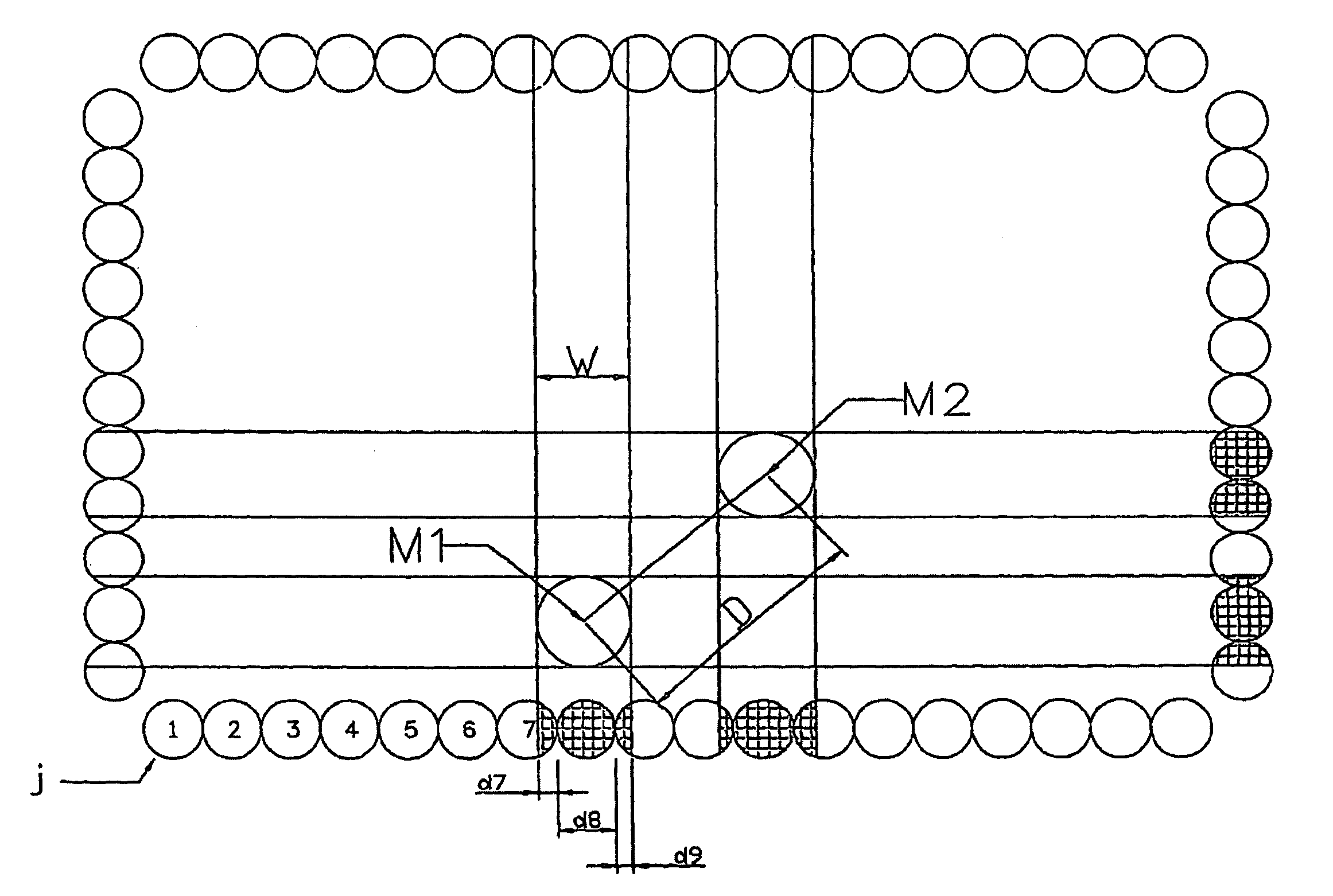
"The invention is an interactive infrared electronic white board that does not require special pens or erasing devices, and has high resolution and durability. It uses two completely integrated emitting and receiving arrays with their own array circuit drivers, making it easy to layout and save circuit board. The invention also uses the inverse square law to increase resolution of infrared beam capturing and realizes an infrared electronic white board with technology using infrared to capture handwriting. The technical effects of this invention are cost-effective, durable, and high-resolution capture capabilities."

Problems solved by technology

However the cost of materials is relatively high and required special electronic pen, making it not very convenient to use; another one comprises plastic membrane with resistance networks on upper and lower layers; under no pressure, the plastic membrane ensure no short circuit through insulating devices; when writing on the board, upper and lower resistance network short circuit under the pressure, and generate different voltage for different positions on the resistance network, thus defines the position of the moving pen through change of voltage.
After prolong use, the plastic membrane is subject to scratch, which causes white noise.
It is also subject to environment factors such as temperature, humidity, which cause the system become unstable; another one uses supersonic technology, i.e., by adding a special supersonic emitting device on the pen, receivers on left and right top corners of the white board, it calculates the distance between the object and receivers through calculating time difference in emitting and receiving supersonic waves, then use algebra principles to reach the track of the whiting pen.
This device needs re-positioning and adjustment before every use and pen must be perpendicular to the writing surface, or errors occur.
Special electronic pens not only increase cost, but also make it less convenient; in order to resolve the special requirement for electronic pens and erasers for existing devices, and dependency on special writing surfaces, this invention provides a kind of white board utilizing infrared beams to capture inputs, but because in traditional infrared touch systems or touch screen technologies, there is limitation on physical dimensions of electro-optical devices such as emitting and receiving diodes, if position of moving object is decided by only replying on whether beams of emitting and receiving diodes on identical light axis is block or not, the maximum resolution of applied white board is the dimension of the emitting or receiving diode.
Even though this technology can improve resolution for a certain level, dead corners caused by physical distribution density of infrared diodes and complexity of calculation can cause some errors, which in turn cause problems in uniformity of resolution and smoothness in capturing objects.
This shows that it is not enough to just copy the current infrared touch screen capturing technologies to electronic white boards to capture tracks (or characters) of moving objects on white boards.

Method used


Image

  • Interactive IR electronic white board
  • Interactive IR electronic white board
  • Interactive IR electronic white board

Examples


Embodiment Construction

[0019]In order to increase resolution of infrared beam scan capturing, this invention establishes a model based on distribution density of light particles on the light path, and by using the relationship between reduction of density of light particles caused by blocking of light path by block objects and variation of output voltages on the receiving diode, establishes a curve equation with a tan(x) function or a quadruple or upper curve equation with the blocking distance as self variable x, and the voltage variation on the receiving diode as the function. The higher the power of the equation, the more precise the results. Normally power of five is enough for satisfactory precision. Of course, under circumstance when high precision if not needed, lineal equation is feasible. By future using this standard equation to calculate concrete blocking positions or widths of blocking objects in the light path, a new method to increase capturing resolution is proposed. By using sequence numbe...


PUM


Abstract

The present invention discloses an interactive IR electronic white board, around which is an infrared emitting and receiving array. An output port of a column driver of emitting array is connected to high frequency modulating signal generator, and an output port of a column driver of the receiving array is connected to a microprocessor through a signal receiving circuit and an analog-digital converter A / D. The emitting array and the receiving array are connected to emitting and the receiving driver through emitting and receiving driver lines, and the emitting driver and the receiving driver are connected with the microprocessor through address bus. The present invention utilizes the Inverse Square Law of optical theory and the linear direct ratio relation between the quantity change of light particles received by an infrared receiving diode and the output voltage of the receiving diode to associate the output voltage of the receiving diode with the interrupted width of the infrared light path, so that it can calculate the coordinate of interrupter accurately and improve the resolution of infrared scanning. The present invention can not only distribute pens or erase, but can be used by plurality of users at the same time as well.

Description

TECHNICAL FIELD[0001]This invention relates to an interactive infrared electronic white boardBACKGROUND ART[0002]Existing electronic white boards are interactive or non-interactive: an interactive white board works with a digital projector to display computer display to the white board, making the white board into a super large interactive computer touch screen. A uses can use fingers to click directly on the white board to operate the computer system and at the same time write, draw or modify contents; while the non-interactive white board can not be connected to a computer, in that the content of the white board can only be stored through printing on paper. There are many kinds of interactive white boards: one use electromagnetic conversion technology and its metal pen generate magnetic field with electric current passing through; when moving on the white board, track of the pen can be deduced based on electromagnetic conversion principle, and is converted and recorded as coordina...

Claims


Application Information

Patent Timeline
Patent Type & Authority Patents(United States)
IPC IPC(8): G06F3/042G06F3/033
CPCG06F3/0421
Inventor HO, WAI
Owner HO WAI
Learn More