Suspension and electro-acoustic transducer using the suspension
a technology of suspension and electroacoustic transducer, which is applied in the direction of transducer diaphragm, loudspeaker diaphragm shape, instruments, etc., can solve the problems of harmonic distortion generated at sound pressure frequency, difficult to maintain suspension compliance, and distortion particularly in the reproduction of low tone area
- Summary
- Abstract
- Description
- Claims
- Application Information
AI Technical Summary
Benefits of technology
Problems solved by technology
Method used
Image
Examples
first exemplary embodiment
[0027]The first exemplary embodiment of the present invention is demonstrated hereinafter with reference to FIG. 1 through FIG. 5.
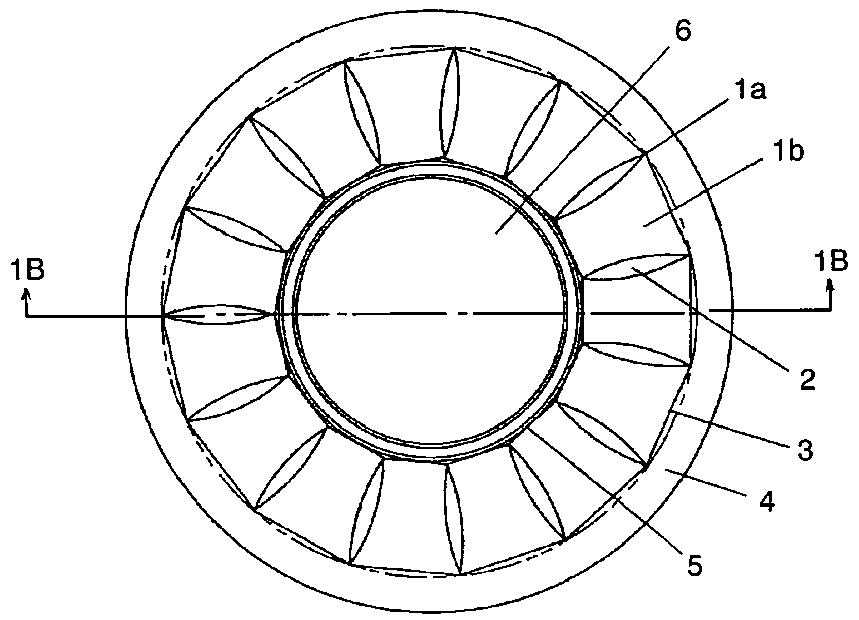
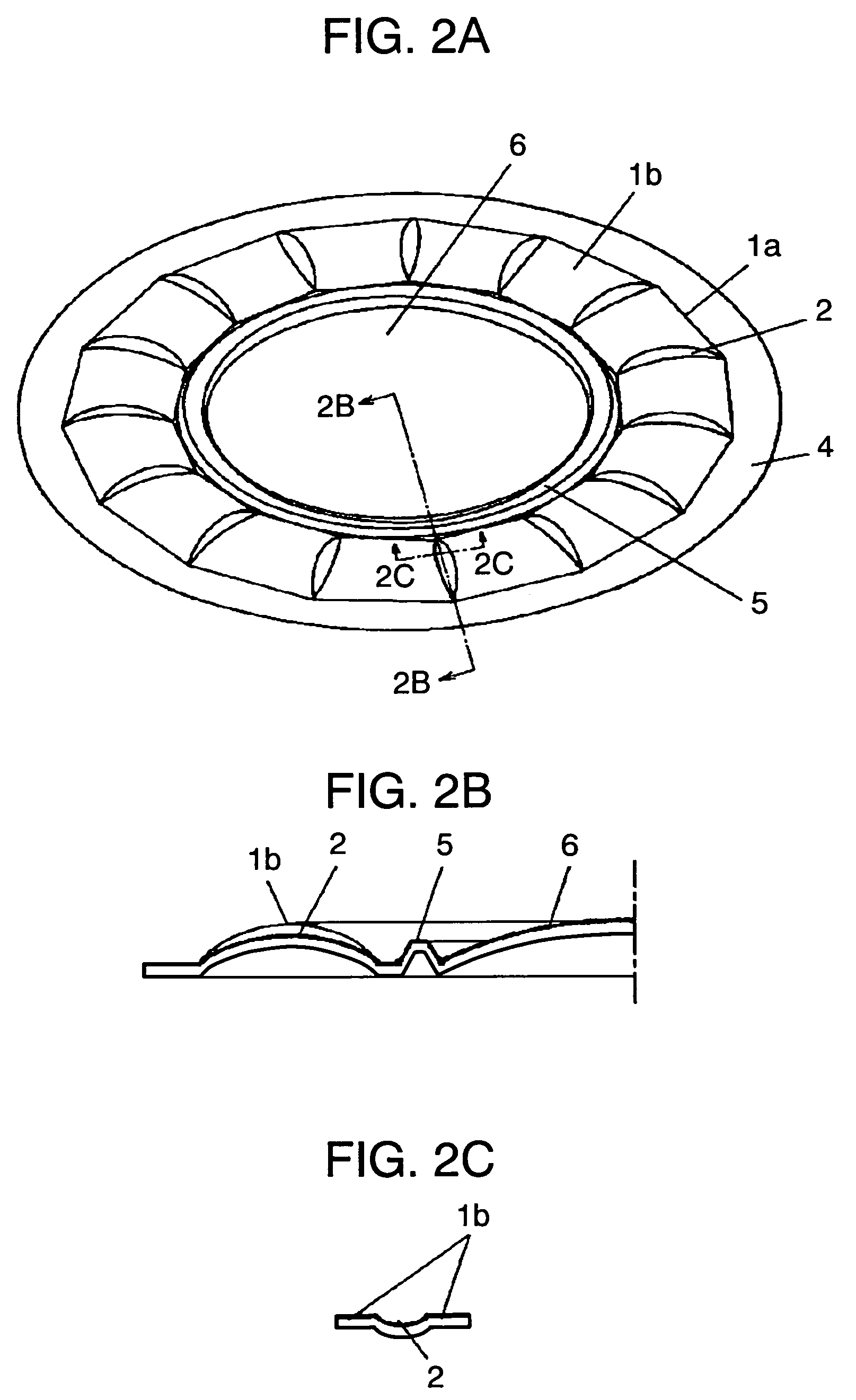
[0028]FIG. 1A is a plan view of a suspension in accordance with the first exemplary embodiment of the present invention. FIG. 1B is a sectional view of FIG. 1A taken along the line 1B-1B. FIG. 2A is a perspective view of FIG. 1A. FIG. 2B is an enlarged sectional view of FIG. 2A taken along the line 2B-2B. FIG. 2C is an enlarged sectional view of FIG. 2A taken along the line 2C-2C. FIG. 3 is a sectional view of an electro-acoustic transducer using the suspension. FIG. 4 is a graph showing a force-displacement characteristic of the suspension in vibration. FIG. 5 shows a condition of the suspension in vibration.
[0029]In FIGS. 1A and 1B, roll sections 1b are disposed radially at a periphery of diaphragm 6 so as to form suspension 1a. Connecting part 3, which is linearly formed, is arranged between frame fixing part 4 and vibration system fixing part 5 is for...
second exemplary embodiment
[0042]The second exemplary embodiment of suspension device 20 of the present invention is demonstrated hereinafter with reference to FIGS. 6A and 6B.
[0043]FIG. 6A is a plan view of suspension device 20 in accordance with the second exemplary embodiment of the present invention. FIG. 6B is a sectional view of FIG. 6A taken along the line 6B-6B.
[0044]Only different point between the first embodiment and the second embodiment is described hereinafter with reference to FIGS. 6A and 6B. Suspensions 1c and 1d each have the same shape as suspension 1a, and are fixed to voice coil 10. Suspension 1c is placed above suspension 1d at a certain distance. Suspension device 20 has suspensions 1c and 1d. Suspension 1c may be fixed to or integrally molded with diaphragm 6.
third exemplary embodiment
[0045]The third exemplary embodiment of suspension device 20 of the present invention is demonstrated hereinafter with reference to FIGS. 7A and 7B.
[0046]FIG. 7A is a plan view of suspension device 20 in accordance with the third exemplary embodiment of the present invention. FIG. 7B is a sectional view of FIG. 7A taken along the line 7B-7B. Suspension device 20 has suspensions 1c and 1d. Suspensions 1c and 1d each have the same shape as suspension 1a, and suspension 1c is shifted from suspension 1d by approximately ½ of width “L” of the roll section in a rotating direction (i.e., a periphery direction).
[0047]In other words, suspensions 1c and 1d are disposed in a substantially vertical direction, and one of suspensions 1c and 1d is rotated by ½ of a width of the roll section with respect to an axis in the periphery direction. Generation of rolling in driving can be prevented when the suspension is mounted in an electro-acoustic transducer.
[0048]Suspensions 1c and 1d are fixed to vo...
PUM
 Abstract
Description
Claims
Application Information
 - R&D
- Intellectual Property
- Life Sciences
- Materials
- Tech Scout
- Unparalleled Data Quality
- Higher Quality Content
- 60% Fewer Hallucinations
Browse by: Latest US Patents, China's latest patents, Technical Efficacy Thesaurus, Application Domain, Technology Topic, Popular Technical Reports.
© 2025 PatSnap. All rights reserved.Legal|Privacy policy|Modern Slavery Act Transparency Statement|Sitemap|About US| Contact US: help@patsnap.com


