
Metal valve stem and sealing system

a sealing system and valve stem technology, applied in the direction of spindle sealing, valve operating means/releasing devices, transportation and packaging, etc., can solve the problems of less durability and reliability, more frequent maintenance and repair, and high cost of sealing systems in deep sea equipmen

Active Publication Date: 2008-09-30
GASOLINEVALVES
View PDF30 Cites 24 Cited by
  • Summary
  • Abstract
  • Description
  • Claims
  • Application Information

AI Technical Summary

Benefits of technology

[0020]The present metal valve stem seal and sealing system can withstand severe deep sea operating conditions, and is reliable, durable and wear resistant, provides an airtight seal to prevent leakage of oil and gas or another fluid, and that complies with the stringent requirements of substantially zero emissions to the environment.
[0021]The present metal valve stem seal and sealing system reduces, minimizes or eliminates the need for maintenance and repair of the sealing system, achieving more permanence of function.
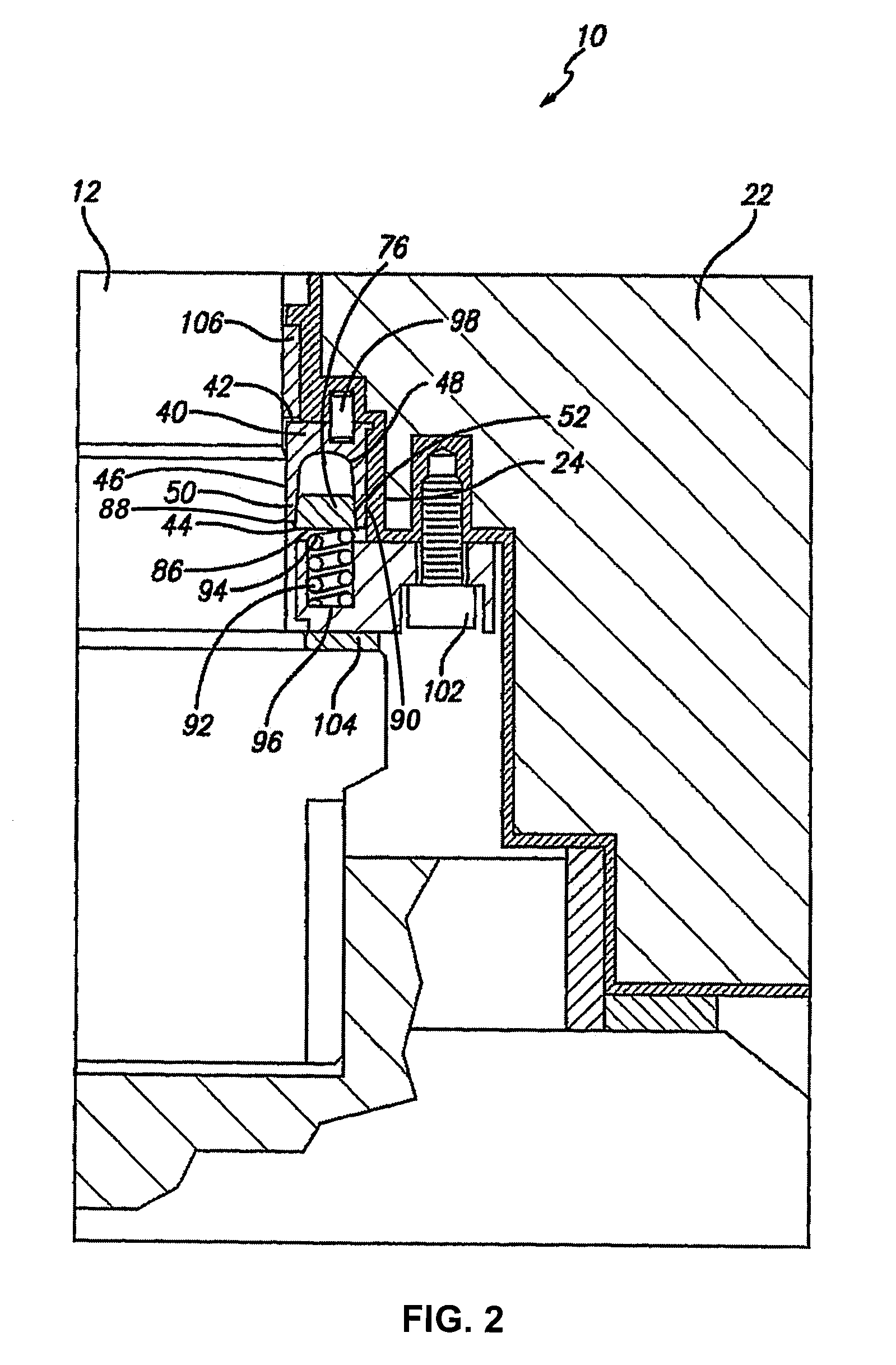
[0024]The present metal valve stem seal and sealing system is mechanically energized through at least one energizing spring situated adjacent a wedge ring, thus providing the required contact stress or force on the sealing area to guarantee an airtight seal at low operating pressure which results in an overall longer life span for the metal valve stem seal and sealing system.

Problems solved by technology

Due to the complex deep sea manmade structures used for deep sea installations, maintenance of the sealing systems in the deep sea equipment is extremely expensive or even impossible to perform.
However, such seals and sealing systems have disadvantages such as insufficient and inadequate sealing capacity under high pressure conditions, premature wearing resulting in less durability and reliability, more frequent maintenance and repair, increased damage to the sealing surfaces, and often the use of more expensive equipment.
Such plastic or elastomeric materials are less advantageous than metals when used in deep sea oil and gas drilling, due to the propensity for the plastic or elastomeric materials to wear out more easily and / or explode under high pressure conditions.

Method used


Image

  • Metal valve stem and sealing system
  • Metal valve stem and sealing system
  • Metal valve stem and sealing system

Examples


Embodiment Construction

)

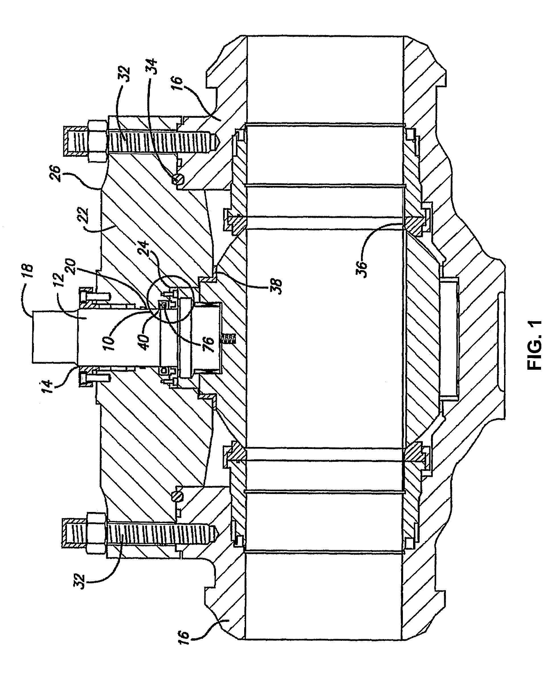
[0030]The present metal valve stem and sealing system provides an improved metal-to-metal valve stem seal for sealing between a movable valve stem and a bonnet member, and an improved sealing system that incorporates the metal-to-metal valve stem seal. Preferably, the present sealing system and metal valve stem seal are used in deep sea equipment used with the drilling of oil and gas and subsea flow lines and pipelines. The present metal valve stem and sealing system can be used with other fluids, such as water and liquid and gaseous hydrocarbons, and can be used for other suitable applications such as with risers which are those structures that connect the underwater sea line to the above water oil and gas drilling platforms.

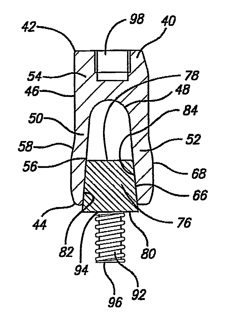
[0031]In an aspect of the present metal valve stem seal and sealing system, a metal valve stem and sealing system 10 is provided, as shown in sectional view in its mechanical environment in FIG. 1, and as shown in an enlarged sectional view in FIG. 2. The meta...


PUM


Abstract

A metal valve stem seal and sealing system includes a valve body, a metal valve stem housed within the valve body, a bonnet member housed within the valve body, and a U-shaped metal stem gasket positioned between the metal valve stem and the bonnet member. The gasket has a first lip member and a second lip member. The metal valve stem seal and sealing system also includes a metal wedge ring fitted between the first and second lip members and at least one metal energizing spring adjacent the wedge ring. The spring applies a sufficient force to the wedge ring to cause the wedge ring to apply a sufficient contact pressure to the first and second lip members to form a seal between the gasket and the metal valve stem and to form a seal between the gasket and the bonnet member.

Description

CROSS-REFERENCE TO RELATED APPLICATION(S)[0001]This application is a continuation of International Application No. PCT / US2004 / 036827, having an international filing date of Nov. 5, 2004, entitled “Metal Valve Stem And Sealing System”. International Application No. PCT / US2004 / 036827 is hereby incorporated by reference herein in its entirety.FIELD OF THE INVENTION[0002]The present invention is directed to metal valve stem seal and sealing system. In particular, the present invention is directed to a metal-to-metal valve stem seal for sealing between a movable valve stem and a bonnet member, and an improved sealing system that incorporates the metal-to-metal valve stem seal. The present sealing system and metal valve stem seal have particular application in the deep sea drilling of oil and gas, and can be used as a sealing system for other fluids, such as water, and liquid and gaseous hydrocarbons, and for other suitable applications such as with risers which are those structures that ...

Claims


Application Information

Patent Timeline
Patent Type & Authority Patents(United States)
IPC IPC(8): F16J15/18
CPCF16J15/3212F16K41/086F16K5/0694F16J15/3236Y10T137/7036
Inventor POZZATI, ROBERTO
Owner GASOLINEVALVES
Learn More