
Method of reducing sulfur dioxide emissions of a circulating fluidized bed boiler

a technology of circulating fluidized bed and boiler, which is applied in the direction of emissions prevention, combustion types, separation processes, etc., can solve the problems of increasing the thermal efficiency of the boiler, reducing the sulfur-reducing additive cost, and producing large amounts of cao-rich ashes, so as to improve the sulfation efficiency, and enhance the sulfation efficiency

Inactive Publication Date: 2008-09-23
FOSTER WHEELER ENERGIA OY
View PDF7 Cites 16 Cited by
  • Summary
  • Abstract
  • Description
  • Claims
  • Application Information

AI Technical Summary

Benefits of technology

[0020]The step of enhancing the calcium carbonate utilization efficiency or the sulfation degree may advantageously comprise the recycling of bottom and / or fly ashes discharged from the boiler back into the furnace. The recycling of the ashes enhances the utilization of the calcium carbonate fed into the furnace, and, thus, modifies the dependence of the sulfur dioxide reduction degree on the Ca / S ratio of the original feed streams. Generally, the recycling of ashes shifts the optimal Ca / S ratio to a lower value, and enhances the advantageous effects of the present invention.
[0021]The step of enhancing the sulfation efficiency or the sulfation degree may advantageously comprise selecting or preparing the average particle size of the sulfur reducing additive to be less than about 200 μm. Alternatively, or additionally, the step of enhancing the sulfation efficiency or the sulfation degree may advantageously comprise using a particle separator in the hot loop having a separation efficiency of at least about 99.9% for particles having an average diameter of 200 μm. The step of enhancing the sulfation efficiency or the sulfation degree may also comprise other known processes, such as enhancing the mixing of particles in the furnace or adjusting temperatures or other conditions in the boiler so as to provide rapid calcination of the calcium carbonate.
[0022]The portion of desired sulfur reduction that is not performed in the furnace is preferably performed downstream of the furnace by one of a dry, semidry, or wet sulfur-reduction process. Various suitable dry, semidry, and wet sulfur-reduction processes are well-known to persons skilled in the art, and, therefore, are not described herein.
[0023]According to another preferred embodiment of the present invention, a method of reducing sulfur dioxide emissions of a circulating fluidized bed boiler comprises steps of (a) feeding a first stream comprising sulfur-containing carbonaceous fuel to a furnace of the boiler; (b) feeding a second stream comprising calcium carbonate to the furnace at a rate relative to the first stream such that the molar ratio of calcium in the second stream to sulfur in the first stream (the Ca / S molar ratio) is at least about 0.6, and at a rate low enough to provide an incremental sulfur-reduction rate of at least about 0.355; (c) combusting the fuel so that the sulfur is oxidized to form sulfur dioxide and ashes are produced in the furnace; (d) calcining the calcium carbonate to form calcium oxide in the furnace and utilizing the calcium oxide to sulfate the sulfur dioxide to form calcium sulfate; (e) discharging flue gases and particles entrained in the flue gases from the furnace; (f) separating the particles from the flue gases using a hot loop separator, and returning the separated particles to the furnace; (g) discharging the ashes from the boiler; and (h) further reducing the sulfur content of the flue gases in a sulfur-reduction stage downstream of the furnace.

Problems solved by technology

This, in turn, increases the sulfur-reducing additive costs, decreases the thermal efficiency of the boiler, and leads to the production of high amounts of CaO-rich ashes.

Method used


Image

  • Method of reducing sulfur dioxide emissions of a circulating fluidized bed boiler
  • Method of reducing sulfur dioxide emissions of a circulating fluidized bed boiler
  • Method of reducing sulfur dioxide emissions of a circulating fluidized bed boiler

Examples


Embodiment Construction

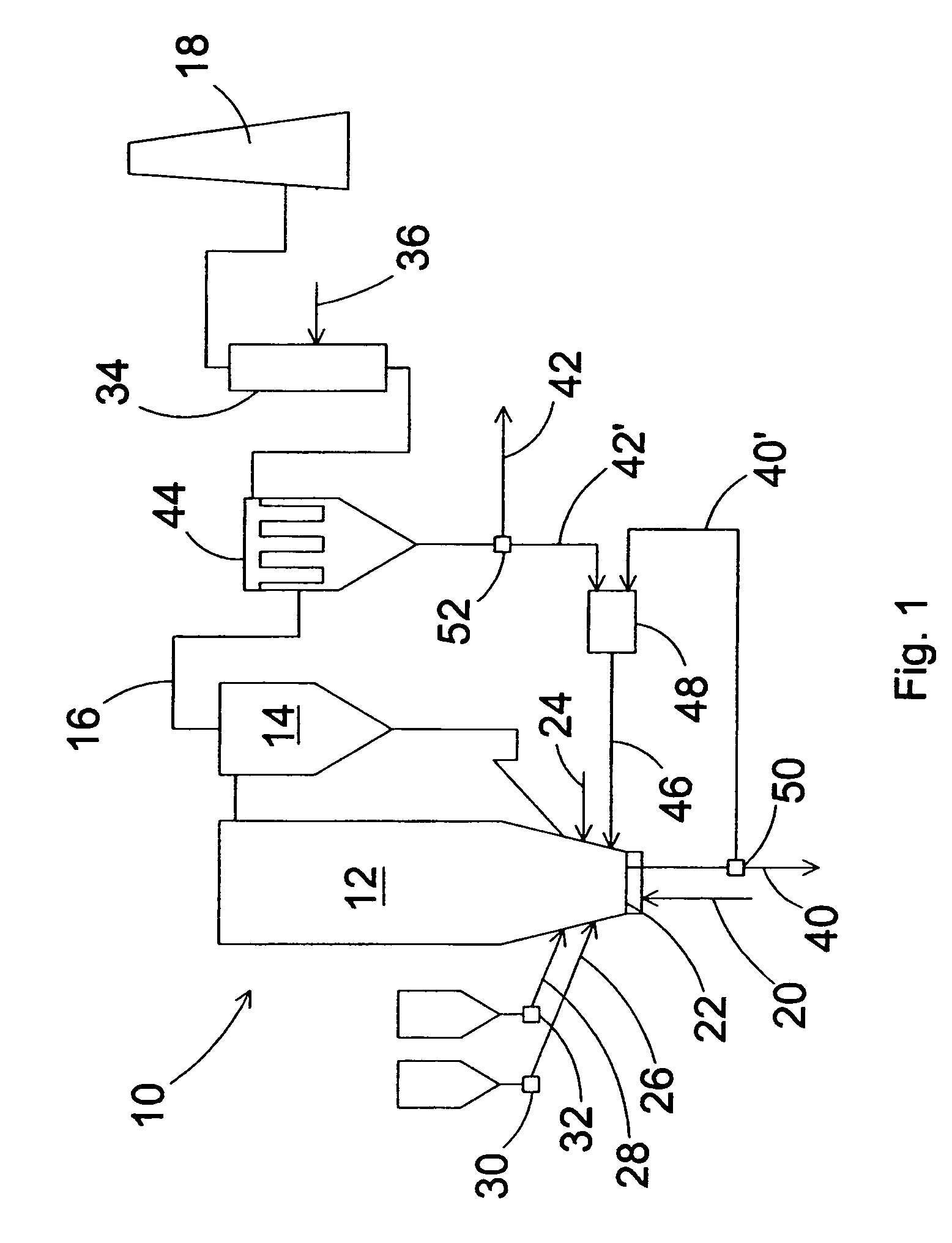
[0027]FIG. 1 schematically illustrates a preferred embodiment of a CFB boiler 10 in accordance with the present invention. The boiler comprises a furnace 12, a cyclone separator 14, and a flue gas channel 16 for directing flue gases discharged from the furnace through a stack 18 to the environment. The furnace 12 includes means 20 for feeding primary air to the furnace through a bottom grid 22, and means 24 for introducing secondary air at a higher level of the furnace. The means 20 for feeding primary air to the furnace may include, for example, a pump, ducting with a flow controller, and a wind box. The means 24 for introducing secondary air may include, for example, branch ducting and a flow controller. Secondary air can be introduced at multiple levels, but for the sake of clarity, a single level is shown in FIG. 1. Although not illustrated in FIG. 1, the flue gas channel 16 optionally may include a heat recovery area.

[0028]The furnace 12 also includes means 26 for feeding fuel ...


PUM

PropertyMeasurementUnit
/S molar ratioaaaaaaaaaa

Abstract

A method of reducing sulfur dioxide emissions of a circulating fluidized bed boiler. Sulfur-containing carbonaceous fuel is fed to a furnace of the boiler, and calcium carbonate is fed to the furnace at a rate relative to the first stream such that the molar ratio of calcium in the second stream to sulfur in the first stream is at most about 1.0. The fuel is combined so that the sulfur is oxidized to form sulfur dioxide. The calcium carbonate is calcined to form calcium oxide and the calcium oxide is used to sulfate the sulfur dioxide to form calcium sulfate. Flue gas particles are separated using a hot loop separator, and the separated particles are returned to the furnace. A sulfur-reduction stage downstream of the furnace further reduces the sulfur content of the flue gases.

Description

BACKGROUND OF THE INVENTION[0001]1. Field of the Invention[0002]The present invention relates to a method of reducing sulfur dioxide emissions of a circulating fluidized bed (CFB) boiler by incorporating a sulfur-reduction stage in the flue gas path.[0003]2. Description of Related Art[0004]Carbonaceous fuel, such as coal, is combusted in the furnace of a CFB boiler in a bed comprising at least one generally inert material, such as sand, and a sulfur dioxide-reducing additive, such as limestone. A fluidizing gas, usually air, is introduced through a bottom grid of the reactor to fluidize the bed material and to oxidize the fuel. Meanwhile, sulfur in the fuel oxidizes mainly to form sulfur dioxide (SO2), which may be harmful if emitted to the environment in large quantities. At the high temperatures prevailing in the furnace, usually from 750° C. to 900° C., calcium carbonate (CaCO3) of the limestone is calcined to form calcium oxide (CaO), which converts the SO2 to calcium sulfate (C...

Claims


Application Information

Patent Timeline
Patent Type & Authority Patents(United States)
IPC IPC(8): B01D53/50C01F11/46F23C10/00F23C10/10F23J15/00
CPCF23C10/002F23C10/10F23J15/006F23J2217/102F23J2215/20F23J2217/101
Inventor KINNUNEN, PERTTI
Owner FOSTER WHEELER ENERGIA OY
Learn More