
Wrench with split ring

a wrench and ring technology, applied in the field of wrenches, can solve problems such as the head sliding

Inactive Publication Date: 2008-09-02
AGS CO AUTOMOTIVE SOLUTIONS LLC
View PDF37 Cites 15 Cited by
  • Summary
  • Abstract
  • Description
  • Claims
  • Application Information

AI Technical Summary

Benefits of technology

[0008]According to the present invention there is provided a one way drive comprising a flexible head having a split aperture therein for loosely engaging drive means for driving a fastener, an elongate handle, and cam means arranged to couple the handle and the flexible head, so that when the one way drive is about to drive a fastener the handle is moved relative to the head, the cam means is effective to close the aperture and increasingly to tighten the flexible head about the drive means as more torque is applied to the handle.

Problems solved by technology

However, if the nut is undersized, damaged or worn, it is very likely that the head will “slip” and rotate around the nut burring the corners instead of properly gripping or engaging the flats or corners of the nut.

Method used


Image

  • Wrench with split ring
  • Wrench with split ring
  • Wrench with split ring

Examples


Embodiment Construction

[0031]Referring more specifically to the drawings, the same reference numerals are used throughout for the same or like parts in all embodiments described below.

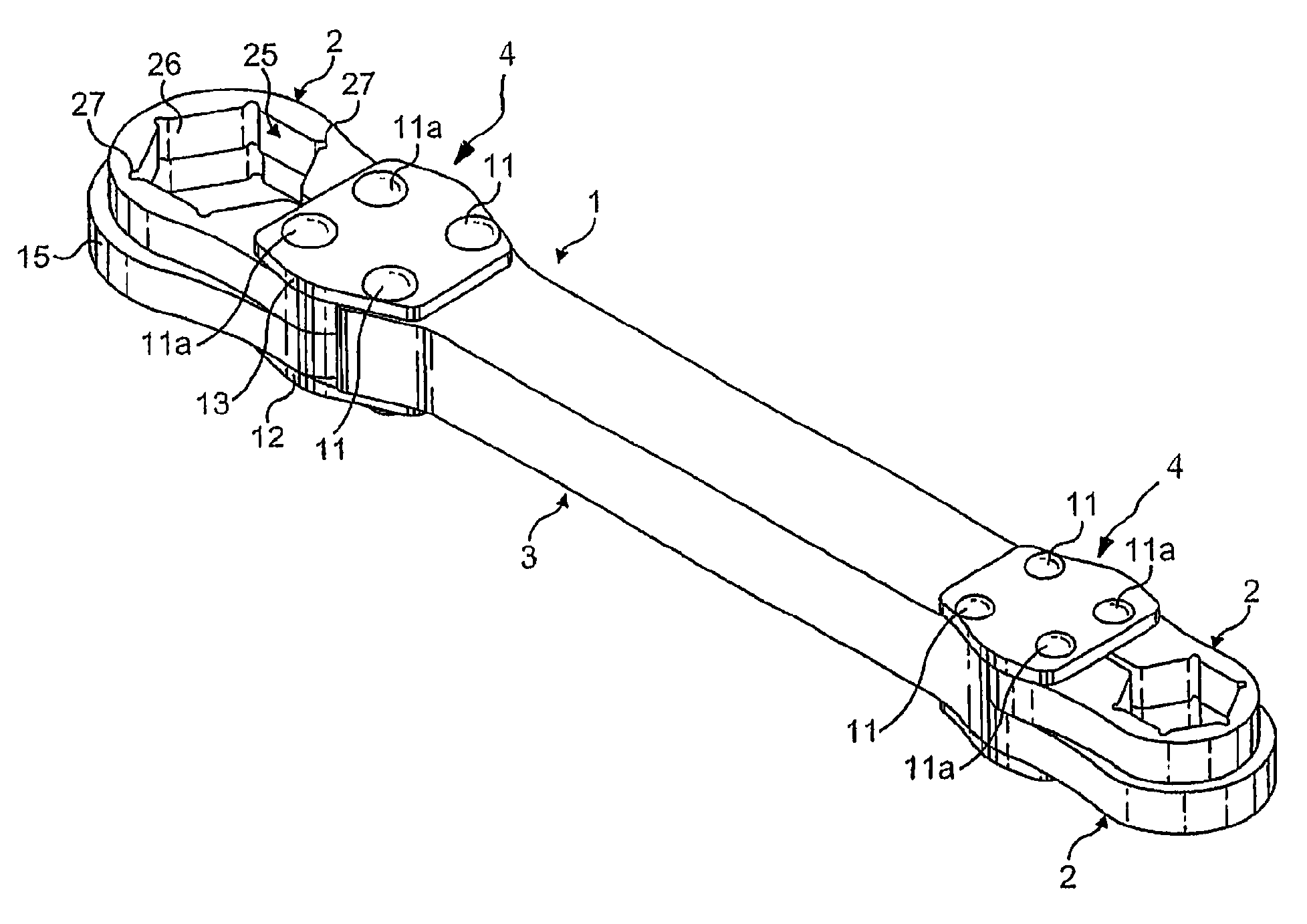
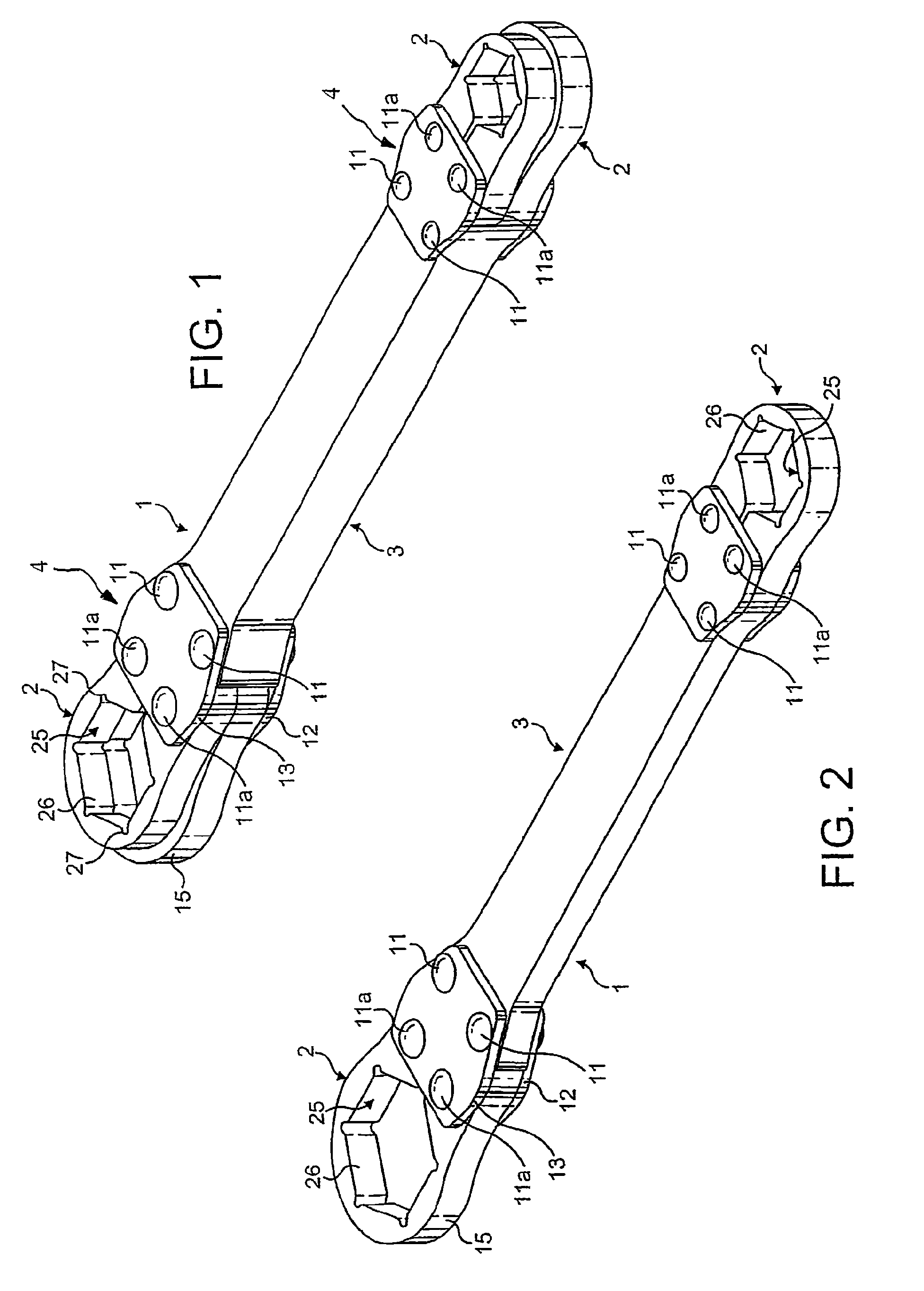
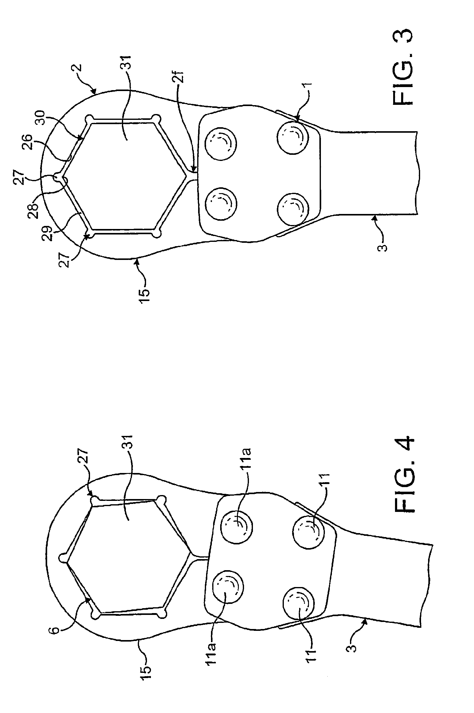
[0032]FIGS. 2 through 6 illustrate one embodiment of a wrench in accordance with the present invention in which a wrench (1) comprises a single flexible ring-like head portion (2), an elongate handle (3) and an intermediate interconnecting portion (4) allowing pivotable movement between the head portion (2) and handle portion (3).

[0033]The handle portion (3) is conveniently of a consistent rectangular cross-section along its length except at each of its opposed ends where the handle has a portion (5) which tapers outwardly as shown more clearly in FIGS. 5 and 6, to terminate in rounded corners (6) extending into a laterally extending flat transverse surface (7) relative to an elongate axis of the handle (3).

[0034]Two circular apertures (9,10) are located in the outwardly tapered portion (5) of the handle (3), at each opposed...


PUM


Abstract

A wrench or one way drive has a flexible head (2) with a split aperture (20) for loosely engaging a separate drive such as a socket or the head of a fastener (31) including a nut, bolt, screw or the like. Cam means, preferably pins (11,11a), are located on a handle (3) and engage the head (2) preferably through slots (21,22) in the head. The slots diverge outwardly so that as the handle is moved relative to the head the split aperture (20) closes and the flexible head (2) increasingly clamps a drive socket as more torque is applied to the handle.

Description

FIELD OF THE INVENTION[0001]The present invention relates to wrenches / one way drive devices also known as “spanners”, and in particular to “ring” type wrenches.BACKGROUND OF THE INVENTION[0002]A wrench is a tool for applying torque to fastener such as a nut, bolt, screw or the like for the purpose of tightening or slackening the fastener. The wrench has a head portion which is of a complementary shape to the periphery of the fastener in a non-rotatable manner so that a force applied to rotate the head transmits torque to the fastener. The fastener usually has an external polygonal shape, typically hexagonal or square, and the head of the wrench has a complementary internal shape and size. The head of a ring wrench is configured to substantially surround the periphery of the fastener.[0003]The following description will refer particularly to wrenches for use with hexagonal nuts. However, it will be understood that the invention is equally applicable to wrenches and corresponding fast...

Claims


Application Information

Patent Timeline
Patent Type & Authority Patents(United States)
IPC IPC(8): B25B13/52B25B13/00B25B17/00B25B13/04B25B13/10B25B13/32B25B13/46
CPCB25B13/04B25B13/56B25B13/46B25B13/32
Inventor BUCHANAN
Owner AGS CO AUTOMOTIVE SOLUTIONS LLC
Learn More