Portable power tool

a power tool and portable technology, applied in the direction of power driven tools, wrenches, screwdrivers, etc., can solve the problems of increased tightening torque, increased torque, and so on, and achieve the effect of improving process reliability and high screwing speed

Active Publication Date: 2021-05-27
C & E FEIN GMBH & CO KG
View PDF10 Cites 0 Cited by
  • Summary
  • Abstract
  • Description
  • Claims
  • Application Information

AI Technical Summary

Benefits of technology

[0007]It is therefore an object of the present invention to reduce the aforementioned disadvantages, in particular to provide a portable power tool which provides improved process reliability at high screwing speeds.

Problems solved by technology

However, when the screwing process is carried out at too high a screw-in speed, there is a risk that the rotational energy is so great that, after releasing the shut-off clutch, the braking time is no longer sufficient to bring the motor to a standstill in a timely manner such that the shut-off clutch is actually released only once.
The repeated release of the shut-off clutch, however, leads to an increased tightening torque and thus to process instability within the screwing process.
If the shut-off clutch is released repeatedly, this is often irritating for the user since by hearing the clicking sound multiple times, the user assumes that the screw fastening has been performed incorrectly.

Method used


Image

  • Portable power tool
  • Portable power tool
  • Portable power tool

Examples


first embodiment

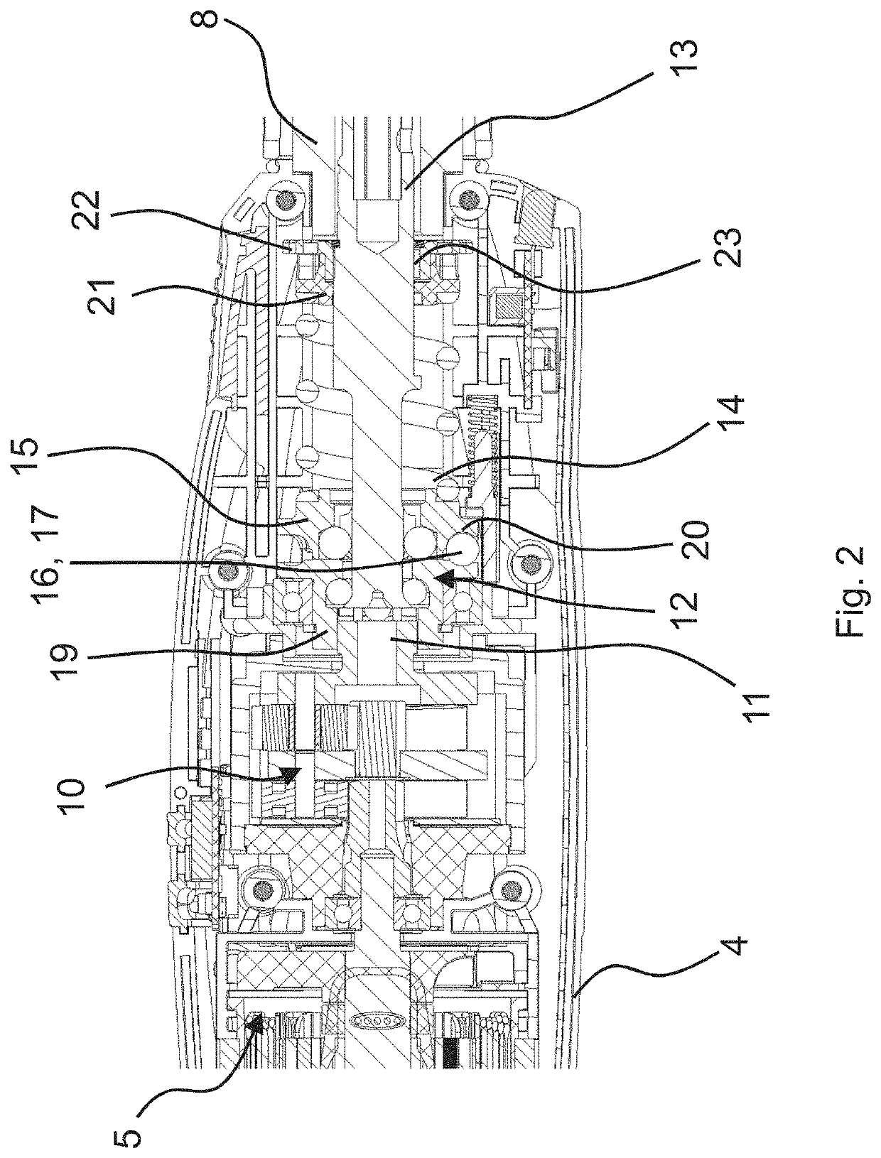
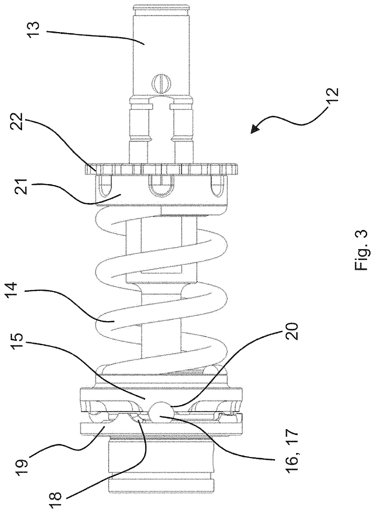
[0037]As can also be seen in particular from FIG. 3, which shows the shut-off clutch 12, the latter comprises a control ring 15 mounted axially against the force of a return spring 14, which is essentially designed to be rotationally fixed to a switch element 16, which in the embodiment is shown as a switching ball 17. The switching ball 17 runs on a control cam 18 which is formed on a cam ring 19 that is non-rotatably connected to the drive shaft 11. The torque applied by the drive 5, coming from the gearbox 10, is introduced in the shut-off clutch 12 on the cam ring 19 and, with a closed shut-off clutch 12, is ultimately transferred to the output unit 13. In this case, the torque is transferred via the switch element 16 from the control cam 18, which is formed on the cam ring 19, to the control ring 15, which is provided in triplicate in the exemplary embodiment shown. The switch elements 16 are each captively received on the control ring 15 in a ball pocket 20, though they have s...

second embodiment

[0041]FIG. 9 shows a perspective view of a control cam 18 of the shut-off clutch 12. Here, the control cam 18 has a first maximum 34, which forms the first switching contour 24 and defines the release torque, and a second maximum 35, which forms the second switching contour 26 and defines the pre-torque. The first maximum 34 is greater than the second maximum 35 and the ratio between the height of the first maximum 34 and the height of the second maximum 35 is 5:1. In addition, the slope of the flank of the first maximum 34 is greater than the slope of the flank of the second maximum 35.

[0042]In a partially sectioned view, FIG. 10 and FIG. 11 show the axial adjustment of the control ring 15 when the applied torque exceeds the pre-torque. In this case, the switch element 16, which is formed as a switching ball 17, is adjusted by the height of the second maximum 35, which forms the pre-torque. Due to the lower height of the second maximum 35 as compared to the first maximum 34, there ...


PUM


Abstract

An electric portable power tool, having a housing, a shaft, a control cam, an electric drive accommodated in the housing to drive the drive shaft, and an output unit that is positively connected with the drive via a mechanical shut-off clutch to transfer torque from the drive to an insertion tool connected with the output unit. The mechanical shut-off clutch comprises a control ring that is axially mounted against the force of the return spring and at least one switch element that is run on the control cam. The control cam is delimited at one end by a first switching contour for providing a release torque of the shut-off clutch and by a boundary contour at another end. The control cam is associated with a second switching contour for providing a pre-torque which is less than the release torque.

Description

[0001]This nonprovisional application claims priority under 35 U.S.C. § 119(a) to German Patent Application No. 20 2019 106 525.7, which was filed in Germany on Nov. 22, 2019, and which is herein incorporated by reference.BACKGROUND OF THE INVENTIONField of the Invention[0002]The present invention relates to an electrical portable power tool, in particular a cordless screwdriver, with a preferably electric drive accommodated in a housing, which drives a drive shaft, with an output unit which can be positively connected to the drive by means of a mechanical shut-off clutch in order to transfer torque from the drive to an insertable tool connected with the output unit, wherein the mechanical shut-off clutch comprises a control ring which is axially supported against the force of a return spring and at least one switch element guided on a control cam, the control cam being limited at one end by a first switching contour for providing a release torque of the shut-off clutch, and at the ...

Claims


Application Information

Patent Timeline
Patent Type & Authority Applications(United States)
IPC IPC(8): B25B21/00B25F5/00
CPCB25B21/00B25F5/001B25B23/147B25B23/141
Inventor MUECK, MICHAELWALZ, FRANK
Owner C & E FEIN GMBH & CO KG
Why Eureka
Try Eureka