
Bucket platform cooling circuit and method

a bucket platform and cooling circuit technology, applied in the direction of leakage prevention, machine/engine, engine manufacture, etc., can solve the problems of stressing the bucket platform, failure before the desired design life, and the difficulty of having the bucket platform last, so as to reduce the stress and temperature of the bucket platform

Inactive Publication Date: 2008-08-26
GENERAL ELECTRIC CO
View PDF29 Cites 113 Cited by
  • Summary
  • Abstract
  • Description
  • Claims
  • Application Information

AI Technical Summary

Benefits of technology

"The invention proposes a new design for the platform of a turbine bucket that reduces stress and temperature. This is achieved by a cooling arrangement that includes a cooling passage in the platform, with inlets and outlets for a cooling medium. The cooling medium flows through the airfoil portion of the turbine bucket and expels through the cooling passage in the platform. This design helps to improve the efficiency and durability of turbine buckets."

Problems solved by technology

Design conditions, that is gas path temperatures and mechanical loads, often create considerable difficulty to have bucket platforms last the desired amount of time in the engine.
In this regard, the loading created by gas turbine buckets create highly stressed regions of the bucket platform that, when coupled with the elevated temperatures, may fail prior to the desired design life.
This adds a great degree of difficulty to pre-installation flow testing.
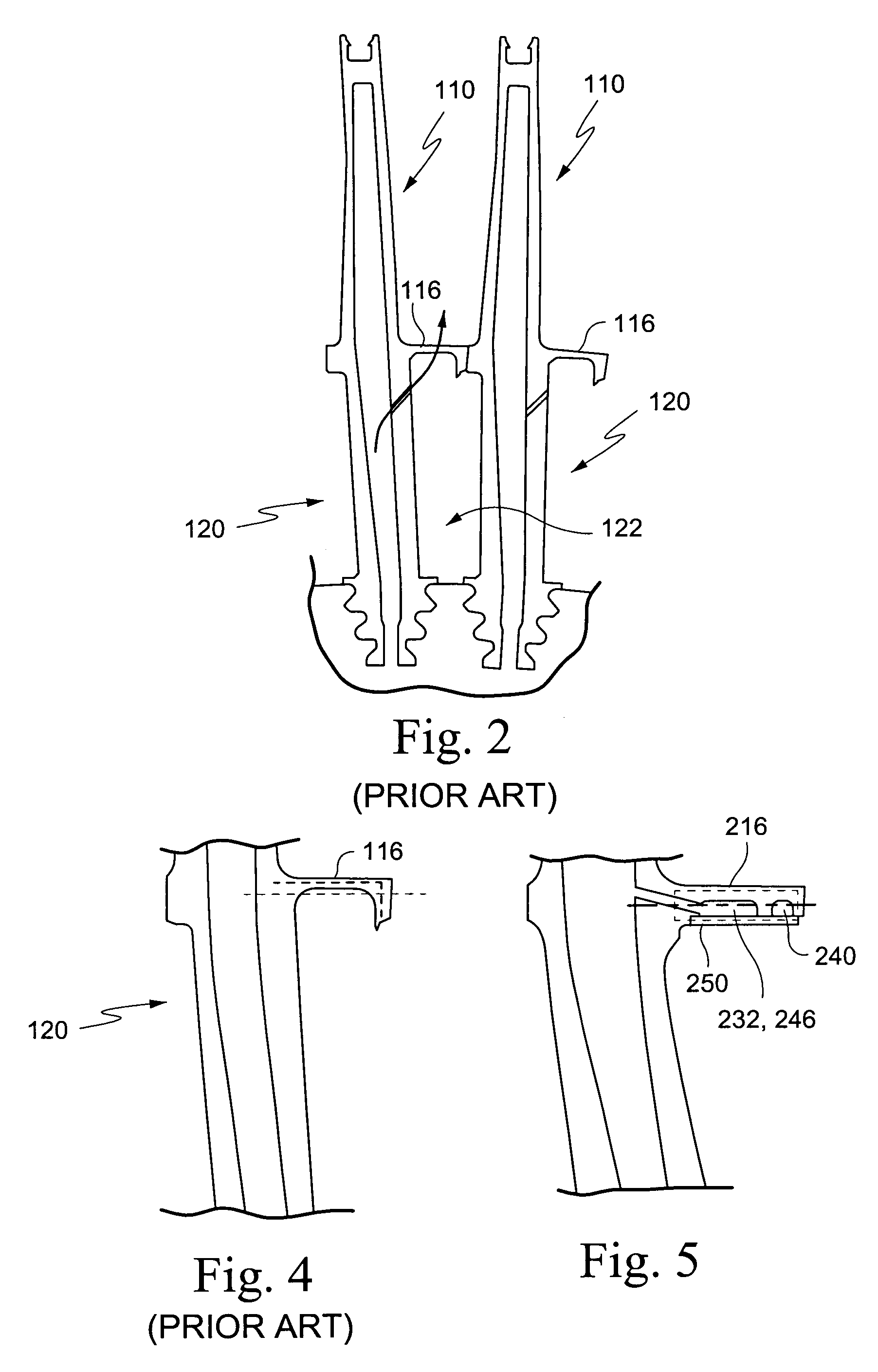
A second disadvantage is the integrity of the cavity 122 formed between adjacent buckets 110 is dependent on how well the perimeter of the cavity is sealed.
Inadequate sealing may result in inadequate platform cooling and wasted cooling air.
However, as illustrated therein, only a single circuit is provided on each side of the airfoil and, thus, there is the disadvantage of having limited control the amount of cooling air used at different locations in the platform.
This design also has the disadvantage of restricting the cooling air supply to the leading edge cavity.

Method used


Image

  • Bucket platform cooling circuit and method
  • Bucket platform cooling circuit and method
  • Bucket platform cooling circuit and method

Examples


Embodiment Construction

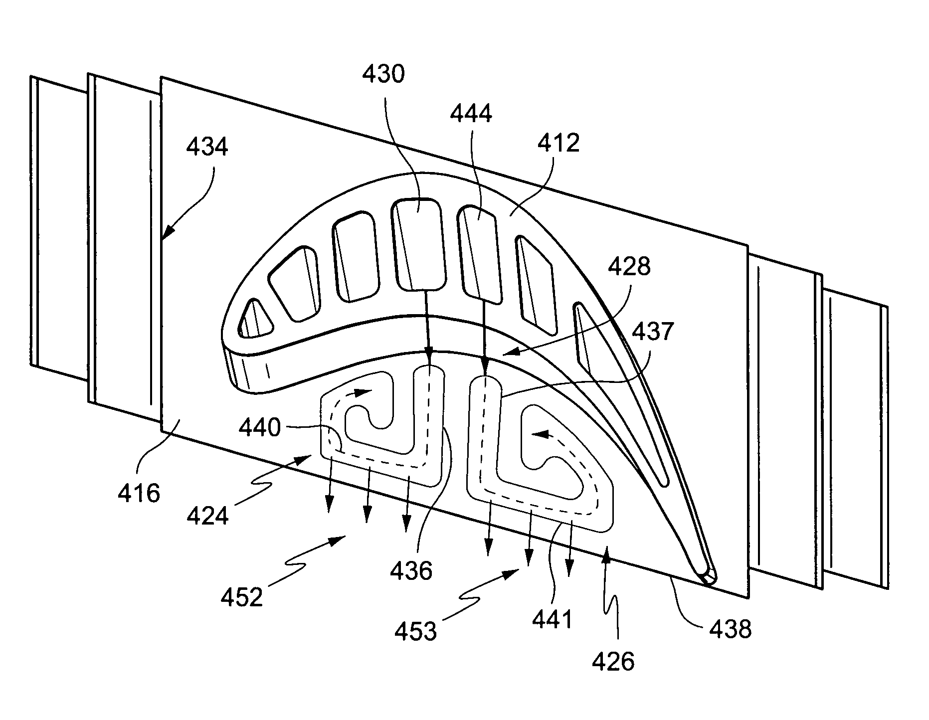
[0023]According to an example embodiment of the invention, one or more preferential cooling passages are defined through the bucket platform on the concave or pressure side of the airfoil as schematically illustrated in FIGS. 3, 6, 7, 8, 9, 10 and 11. These cooling passages are supplied with a cooling medium, such as air, from the airfoil cooling circuit, more specifically from a vicinity of an axial center or mid-section of the respective airfoil. In the illustrated examples, where plural cooling passages are provided, each is supplied with air from a respective airfoil cooling circuit cavity or passage.

[0024]The cooling passages are respectively sized and shaped to accomplish at least two goals. First, the passages are defined to allow for a preferential cooling of the platform. Preferential cooling allows the correct amount of cooling to be performed at various locations on the platform.

[0025]Referring by way of example to FIG. 3, it can be seen that in this example embodiment, t...


PUM


Abstract

In a turbine bucket having an airfoil portion and a root portion with a platform at an interface between the airfoil portion and the root portion, a platform cooling arrangement including: a cooling passage defined in the platform to extend along at least a portion of a concave, pressure side of the airfoil portion, at least one cooling medium inlet to said cooling passage extending from an airfoil cooling medium cavity in a vicinity of an axial center of the airfoil portion, and at least one outlet opening for expelling cooling medium from said cooling passage.

Description

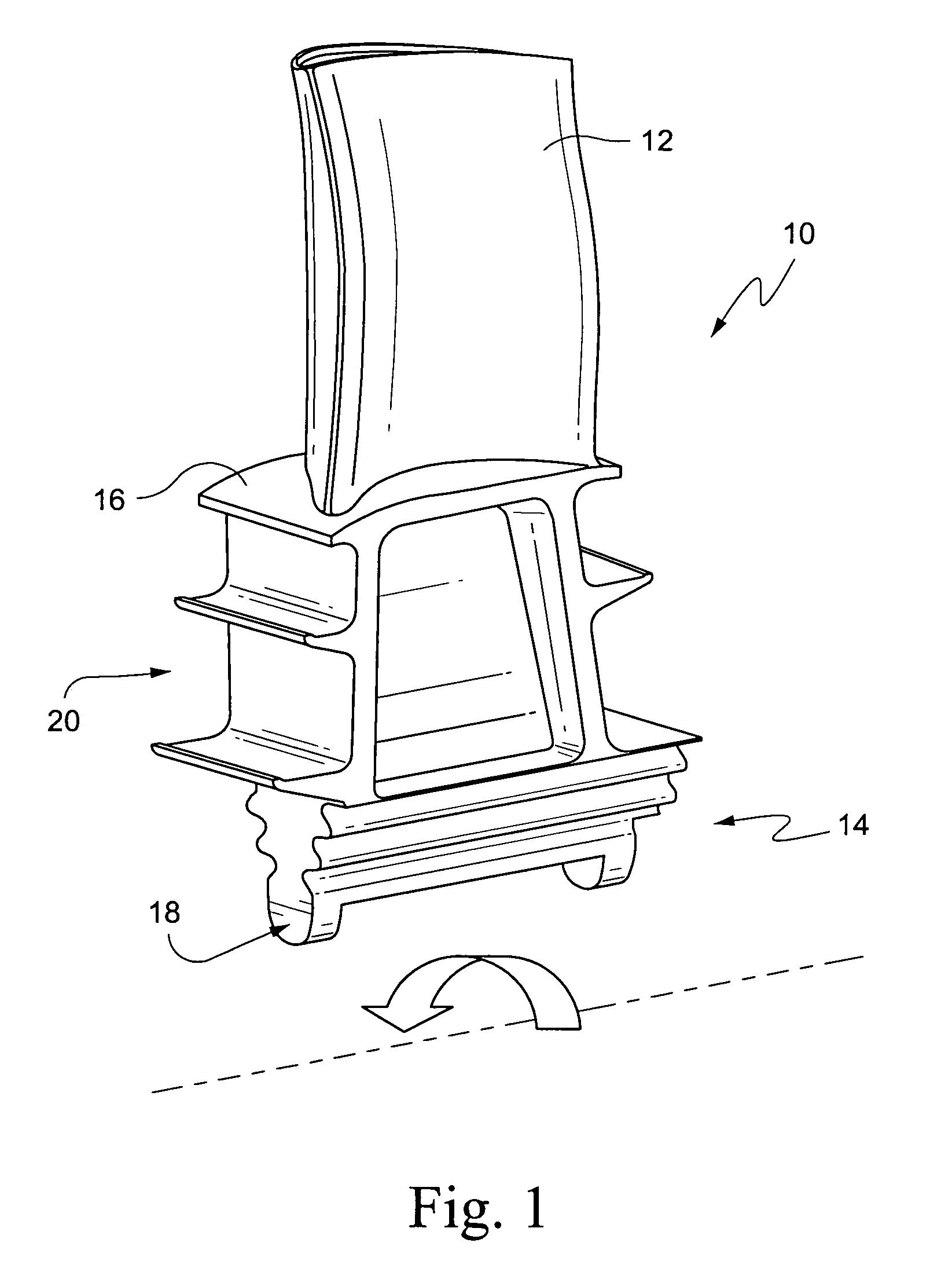
BACKGROUND OF THE INVENTION[0001]The present invention relates to a novel cooling system for increasing the useful life of a turbine bucket.[0002]A gas turbine has (i) a compressor section for producing compressed air, (ii) a combustion section for heating a first portion of said compressed air, thereby producing a hot compressed gas, and (iii) a turbine section having a rotor disposed therein for expanding the hot compressed gas. The rotor is comprised of a plurality of circumferentially disposed turbine buckets.[0003]Referring to FIG. 1, each turbine bucket 10 is comprised of an airfoil portion 12 having a suction surface and a pressure surface; and a root portion 14 having structure 18 to affixing the blade to the rotor shaft, a platform 16 from which said airfoil extends, and a shank portion 20.[0004]The platforms are employed on turbine buckets to form the inner flow path boundary through the hot gas path section of the gas turbine. Design conditions, that is gas path temperatu...

Claims


Application Information

Patent Timeline
Patent Type & Authority Patents(United States)
IPC IPC(8): F01D5/18
CPCF01D5/187F05D2250/185F05D2260/205F05D2260/202F05D2240/81F01D5/18F01D5/14
Inventor VELTRE, LOUISMACARIAN, CHRISTOPHER ARDA
Owner GENERAL ELECTRIC CO
Learn More