


Quick Research
Generate reliable direction feasibility study reports for your R&D in just a few steps.

Technical Q&A
Discover and master advanced knowledge NOW. Basics, ideas, possibilities, all at once.

Find Solutions
As an expert in R&D theories, this can generate solutions to your technical problems instantly.

Evaluate Feasibility
Analyze your overall solution with one click, know your potential R&D risks in advance.

Monitor Landscape
Get weekly tech updates, stay abreast of the latest tech innovations and key insights.
Power control device for an electrical load
a power control device and load technology, applied in the direction of coupling device connections, contact mechanisms, lighting and heating apparatus, etc., can solve the problems of conventional devices relating to cleaning and maintenance issues of devices, additional costs and complexity of the frame itself, etc., to eliminate cleaning and maintenance problems
- Summary
- Abstract
- Description
- Claims
- Application Information
AI Technical Summary
Benefits of technology
Problems solved by technology
Method used
Image

Examples
first embodiment
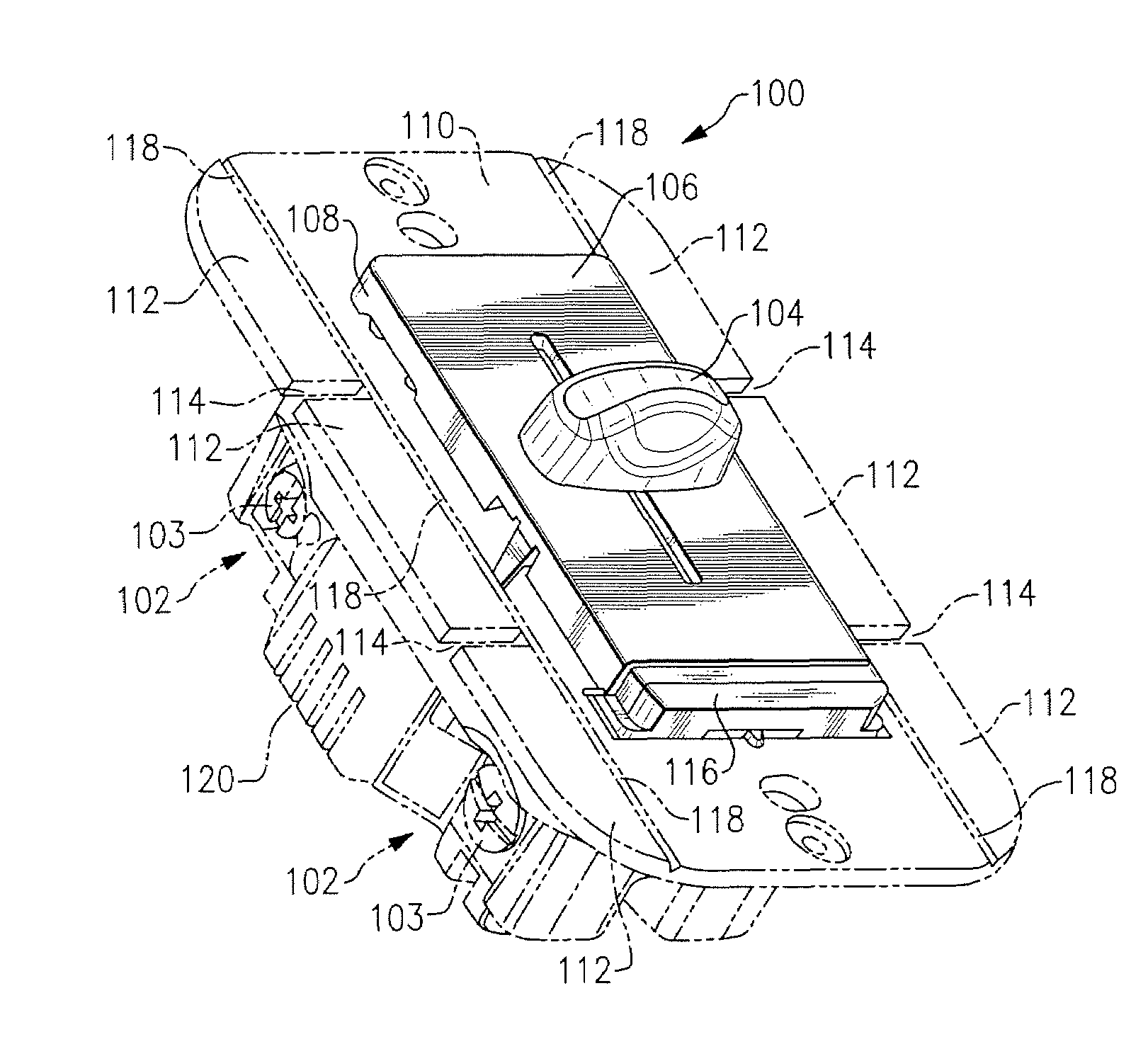
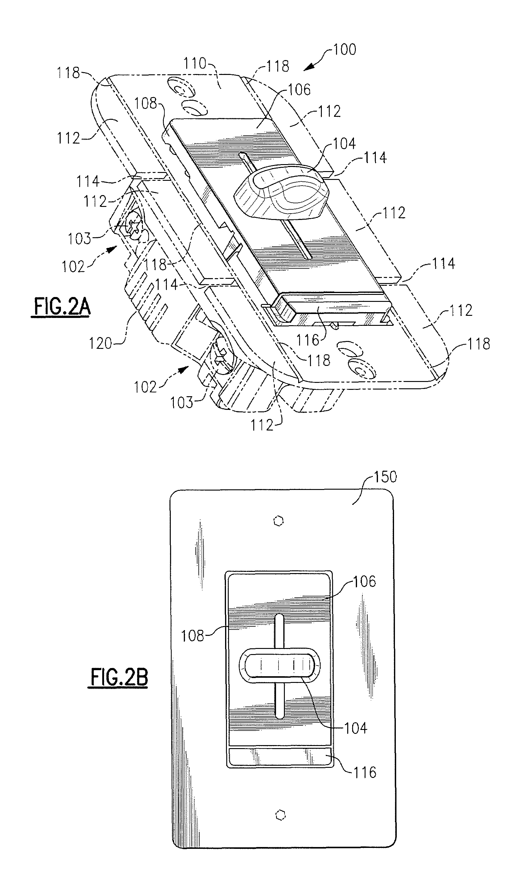
[0043]As embodied herein and depicted in FIG. 2A, a perspective view of the power control device is shown. Device 100 includes a mounting strap 110, which functions as the device heat sink, coupled between a user accessible front cover portion 106 and device body member 120. A light module 116 is disposed between cover member 106 and an end portion of front cover portion 106. Device 100 includes screw terminals 102 which are provided to connect device 100 to both the voltage source and the load. A control knob 104 is disposed on the user accessible cover member 106 and is employed to adjust the power delivered to the load.
[0044]Power control device 100 may include a light module 116. Light module 116 may be configured to emit light when the control knob 104 is in the full OFF position. In this embodiment, lamp 116 operates as a locator for power control device 100 such that device 100 may be located by a user in a darkened room. In an alternate embodiment, lamp 116 serves as a pilot...
second embodiment
[0066]the present invention also includes a light module 116. Again, the light module 116 functions as a locator light. When switch 1260 is placed in the OFF position, current is applied to the light module 116. Light is thus emitted when device 100 is turned OFF. Thus, a person entering a darkened room may easily locate the control because the light emitted by module 116 functions as a location beacon.
[0067]Switch 1260 operates as follows. Control knob 104 is shown in the OFF position. In the OFF position, switch contacts 1 and 3 are shorted together by shorting structure 1262 and contacts 2 and 4 are shorted together by shorting structure 1264. As the switch is stepped from the OFF position to the MAX position, the bridging structures advance each time to short the next pair of adjacent terminals. When knob 104 is stepped all the way to the MAX position, contacts 9 and 11 are shorted together and contacts 10 and 12 are shorted together. At the MAX position, there is little or no i...
third embodiment
[0072]As embodied herein and depicted in FIG. 8A, a perspective view of a power control device 110 in accordance with the present invention is shown. In this embodiment, the self-aligning front cover member includes the dimmer switch front portion 106 and a switch element 300. Of course, the light module 116 is disposed under the switch element 300. Each of these elements (106, 300, 116) has a raised rectangular form factor that corresponds to a standard wall plate opening. Switch 300 also includes raised edges 302 that are configured to align with the raised edge of dimmer cover member 106 and light module 116. Raised edges 302, light module 116, and dimmer cover member 106 are configured to be flush, or slightly raised, relative to the surface of the cover plate 150.
[0073]Those of ordinary skill in the art will understand that control knob 104 may be coupled to either a continuously variable dimmer control or a variable speed fan control disposed in body member 120. Thus, switch c...
PUM
 Abstract
Description
Claims
Application Information
 - R&D Engineer
- R&D Manager
- IP Professional
- Industry Leading Data Capabilities
- Powerful AI technology
- Patent DNA Extraction
Browse by: Latest US Patents, China's latest patents, Technical Efficacy Thesaurus, Application Domain, Technology Topic, Popular Technical Reports.
© 2024 PatSnap. All rights reserved.Legal|Privacy policy|Modern Slavery Act Transparency Statement|Sitemap|About US| Contact US: help@patsnap.com