
Tuning low-inductance coils at low frequencies

a low-frequency, coil technology, applied in the field of resonance electrical circuits, can solve problems such as and achieve the effect of reducing the range of adjustability

Inactive Publication Date: 2008-07-29
ABQMR
View PDF14 Cites 57 Cited by
  • Summary
  • Abstract
  • Description
  • Claims
  • Application Information

AI Technical Summary

Benefits of technology

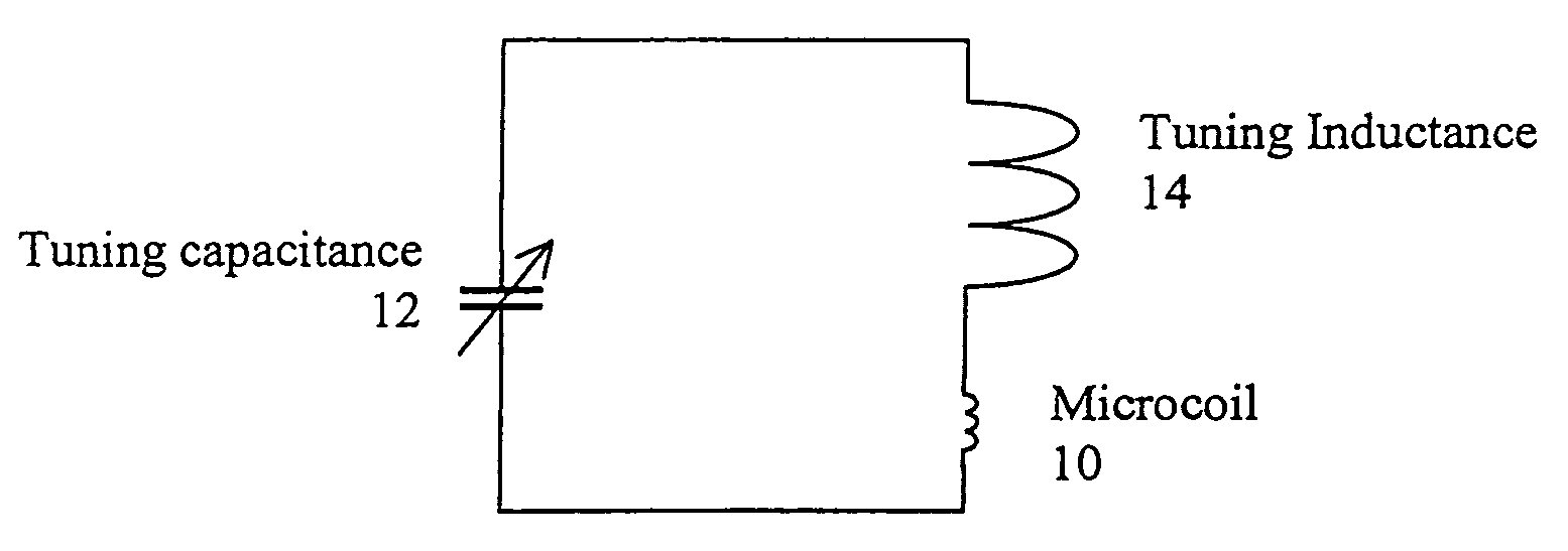
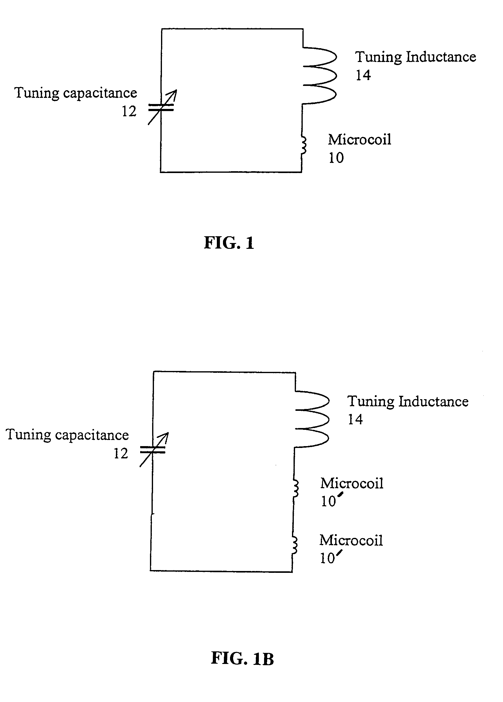
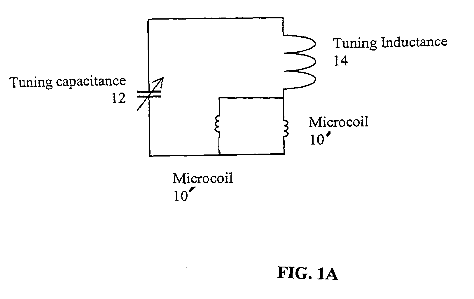
"The patent describes an apparatus and method for tuning low-inductance coils at low frequencies. The invention includes a microcoil, an adjustable tuning capacitance, and a tuning inductor. The inclusion of the tuning inductor helps to reduce the capacitance required for resonance and apparatus function. The invention allows for the miniaturization of coils used in resonant circuits, as well as the operation of small coils at arbitrarily low frequencies. The invention also allows for the miniaturization of small coils used in NMR and MRI, and works with a multiplicity of small coils. The invention's technical effects include reducing the size of coils, enabling the operation of small coils at low frequencies, and minimizing the impact of the tuning capacitance and inductance on the magnetic field at the sample."

Problems solved by technology

(1) the use of physically large adjustable capacitors;
(2) the use of high-fixed-value capacitors together with a variable capacitor, which reduces the range of adjustability; and

Method used


Image

  • Tuning low-inductance coils at low frequencies
  • Tuning low-inductance coils at low frequencies
  • Tuning low-inductance coils at low frequencies

Examples


Embodiment Construction

)

[0055]There is disclosed herein an apparatus and method for tuning low-inductance coils at low frequencies. A purpose of the disclosed apparatus and method is to allow a very small coil of negligible inductance to be resonated electrically at low frequency, while readily maintaining frequency adjustability over a wide range of values using standard variable capacitors. “Low frequency,” in this application, means less than about 100 MHz. The main application of the disclosed circuitry is in the field of Nuclear Magnetic Resonance (NMR), although it is useful for any situation requiring a tunable resonant circuit containing a very small coil. Properly implemented, the disclosed circuit introduces few or no electrical losses into the resonant circuit, and the circuit maintains maximal efficiency for the detection of NMR signals.

[0056]The disclosure includes a LC resonance circuit that would be appropriate for performing magnetic resonance experiments, among other beneficial purposes. ...


PUM


Abstract

A method and apparatus for tuning and matching extremely small sample coils with very low inductance for use in magnetic resonance experiments conducted at low frequencies. A circuit is disclosed that is appropriate for performing measurements in fields where magnetic resonance is beneficially utilized. The circuit has a microcoil, an adjustable tuning capacitance, and added inductance in the form of a tuning inductor. The microcoil is an electrical coil having an inductance of about 25 nanohenries (nH) or less. Because additional inductance is purposefully added, the capacitance required for resonance and apparatus function is proportionally and helpfully reduced. The apparatus and method permit the resonant circuit and the magnet to be made extremely small, which is crucial for new applications in portable magnetic resonance imaging, for example.

Description

BACKGROUND OF THE INVENTION[0001]1. Field of the Invention (Technical Field)[0002]The present invention relates to resonant electrical circuits containing inductors and capacitors, particularly when the inductance is very low and the circuit must resonate at a low frequency. More specifically, this disclosure is directed to a method for tuning and matching extremely small sample coils with very low inductance for use in magnetic resonance experiments conducted at low frequencies.[0003]2. Background Art[0004]Magnetic resonance experiments and procedures typically are performed using an electrically resonant circuit, with a coil (inductor L) wrapped around a sample to be evaluated, and a capacitor (capacitance C) connected to the coil to form a series or parallel resonant LC circuit. The frequency at which the electrical resonance must occur is determined by the strength of the magnetic field used, as well as the properties of the nucleus (or electron) being studied.[0005]The arts of ...

Claims


Application Information

Patent Timeline
Patent Type & Authority Patents(United States)
IPC IPC(8): G01V3/00
CPCG01R33/3628G01R33/34
Inventor MCDOWELL, ANDREW F.
Owner ABQMR
Learn More