
Image reading apparatus

a technology of image data and reading surface, which is applied in the field of image data reading apparatus, can solve the problems of difficult to make the illuminance uniform on the light receiving surface of a ccd sensor, the intensity of light passing through the center and periphery of a lens is not constant, and the dignity of image data is increased

Inactive Publication Date: 2008-07-15
KK TOSHIBA +1
View PDF6 Cites 3 Cited by
  • Summary
  • Abstract
  • Description
  • Claims
  • Application Information

AI Technical Summary

Benefits of technology

The present invention aims to improve the quality of image data obtained by an image reading sensor. This is achieved by optimizing the distribution of light radiated from a lamp of an illumination unit with respect to the length direction of the illumination unit. The invention provides an image reading apparatus comprising a light-emitting unit, an opto-electric conversion element, and an optical element, which guides the light from the reading object to the opto-electric conversion element. Additionally, the invention provides an illumination unit comprising a tubular glass, a luminous particle, an electrode member, and a window area. The invention allows for improved image quality and provides a more efficient and effective image reading process.

Problems solved by technology

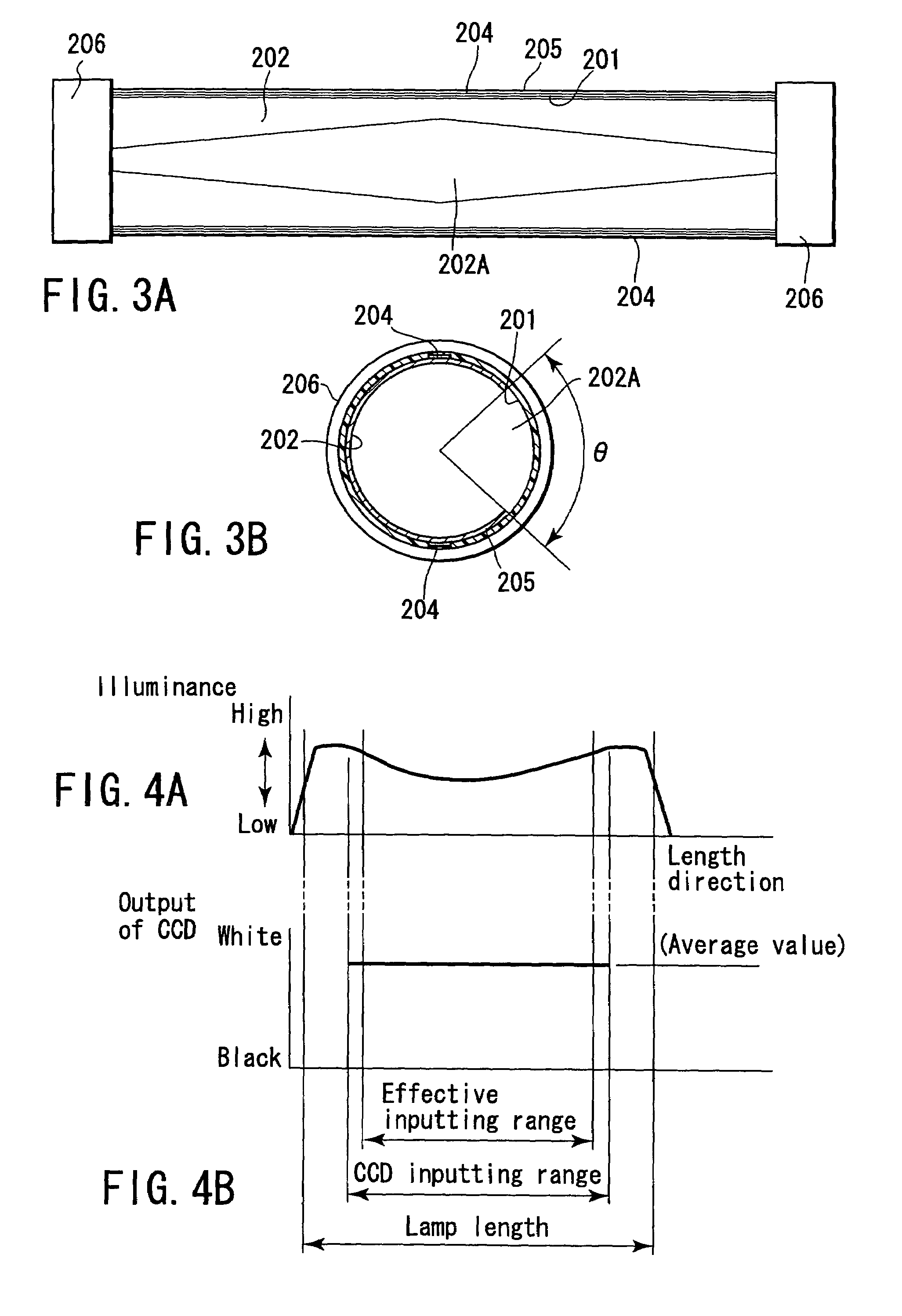
However, when a reduction lens is used, the intensities of the light passing through the center and periphery of a lens are not constant, and it is known that the light intensity lowers as the light shifts from the lens center, according to the well-known cosine biquadratic law.
However, even if a xenon lamp with the external electrode shaped as above is used, it is difficult to make the illuminance uniform on the light receiving surface of a CCD sensor.
Moreover, the characterizing the external electrode shape of a xenon lamp increases the cost of the lamp.

Method used


Image

  • Image reading apparatus
  • Image reading apparatus
  • Image reading apparatus

Examples


Embodiment Construction

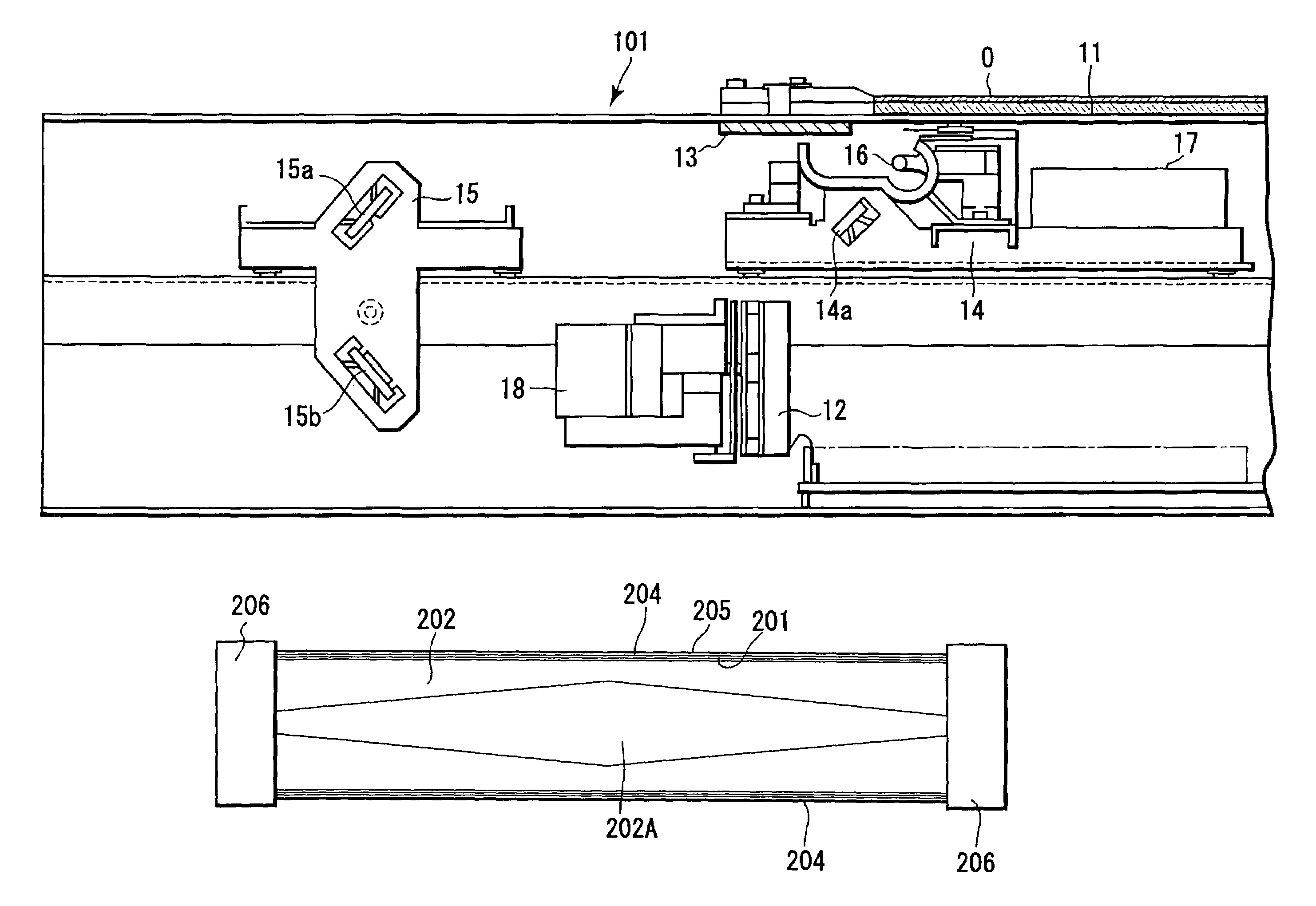
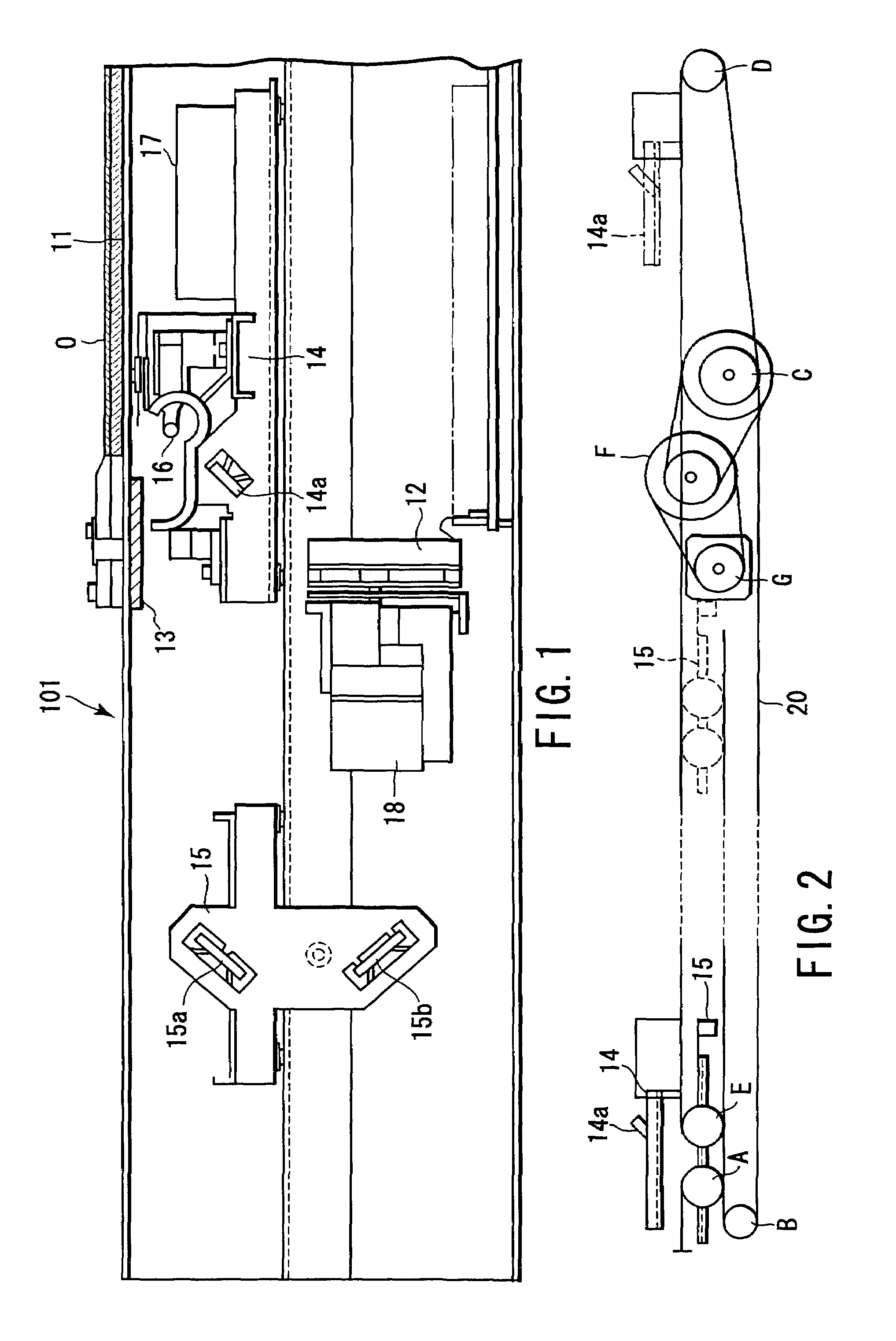
[0034]Hereinafter, an example of an image reading apparatus to which an embodiment of the present invention is applicable will be explained with reference to the accompanying drawings.

[0035]As shown in FIG. 1, an image reading apparatus (scanner) 101 has a document table 11 which is a transparent plate-like plain body made of light transmitting material, represented by glass, with the substantially even thickness. The document table 11 holds a copying object O. Hereinafter, the reading object O is called a document, assuming that the reading object O is sheet-like.

[0036]At a predetermined position in a scanner 101 below the document table 11, a CCD sensor 12 which converts the image information of the reading object O to an electric signal (image signal) is provided.

[0037]At a predetermined position close to one side of the document table 11, a white reference plate 13 used to set a white reference value of the CCD sensor 12 is provided.

[0038]In the space below the document table 11...


PUM


Abstract

An image reading apparatus according to the present invention can obtain an image light from all areas of a document with uniform brightness, when receiving an image light from an area elongate in a first direction, and obtaining image data corresponding to the image information of a document by moving the image light area in a direction orthogonal to the first direction.

Description

BACKGROUND OF THE INVENTION[0001]The present invention relates to an image reading apparatus which obtains image data from a reading object.[0002]An image scanner obtains image data by opto-electrically converting a reflected light obtained by illuminating a sheet-like document, a book or a three-dimensional reading object, by an image reading sensor.[0003]An image scanner is a transparent glass plate, for example, and includes a document holder (a document table) to hold a reading object placed on a document table, an illumination lamp, an illumination unit to illuminate a reading object placed on a document table, a line CCD sensor or an image reading sensor, and an image forming lens provided between a document table and a CCD sensor, to apply a reflected light from a reading object to a CCD sensor. An image forming lens is a reduction lens to reduce a reflected light of a reading width (length) defined as the length of one side of a document table, to meet the width (length) of ...

Claims


Application Information

Patent Timeline
Patent Type & Authority Patents(United States)
IPC IPC(8): H04N1/04H04N1/46
CPCH04N1/1013H04N1/02815
Inventor IDE, NAOAKI
Owner KK TOSHIBA
Learn More