
Reciprocating saw

a saw and reciprocating technology, applied in the field of reciprocating saws, can solve the problems of operator troublesome operations, guide shoe cannot be locked in this location, operator cannot recognize whether the guide shoe is in a location, etc., and achieve the effect of convenient location fixation

Inactive Publication Date: 2008-07-08
MAKITA CORP
View PDF7 Cites 18 Cited by
  • Summary
  • Abstract
  • Description
  • Claims
  • Application Information

AI Technical Summary

Benefits of technology

[0013]The present invention solves the aforementioned problem. It is thus one object of the present invention to provide techniques for enabling an operator to recognize whether the guide shoe is in a location that allows locking while adjusting the location of the guide shoe.
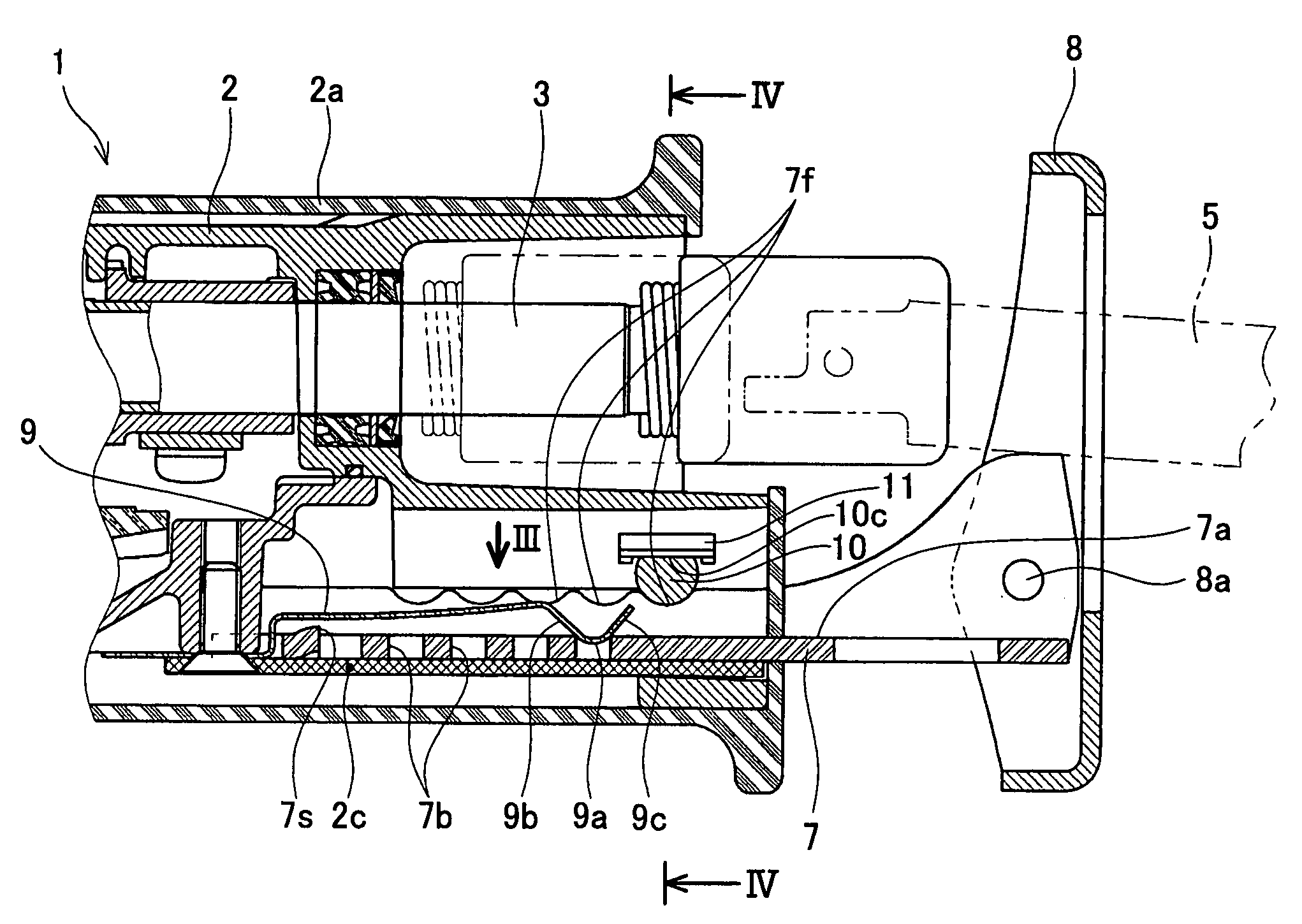
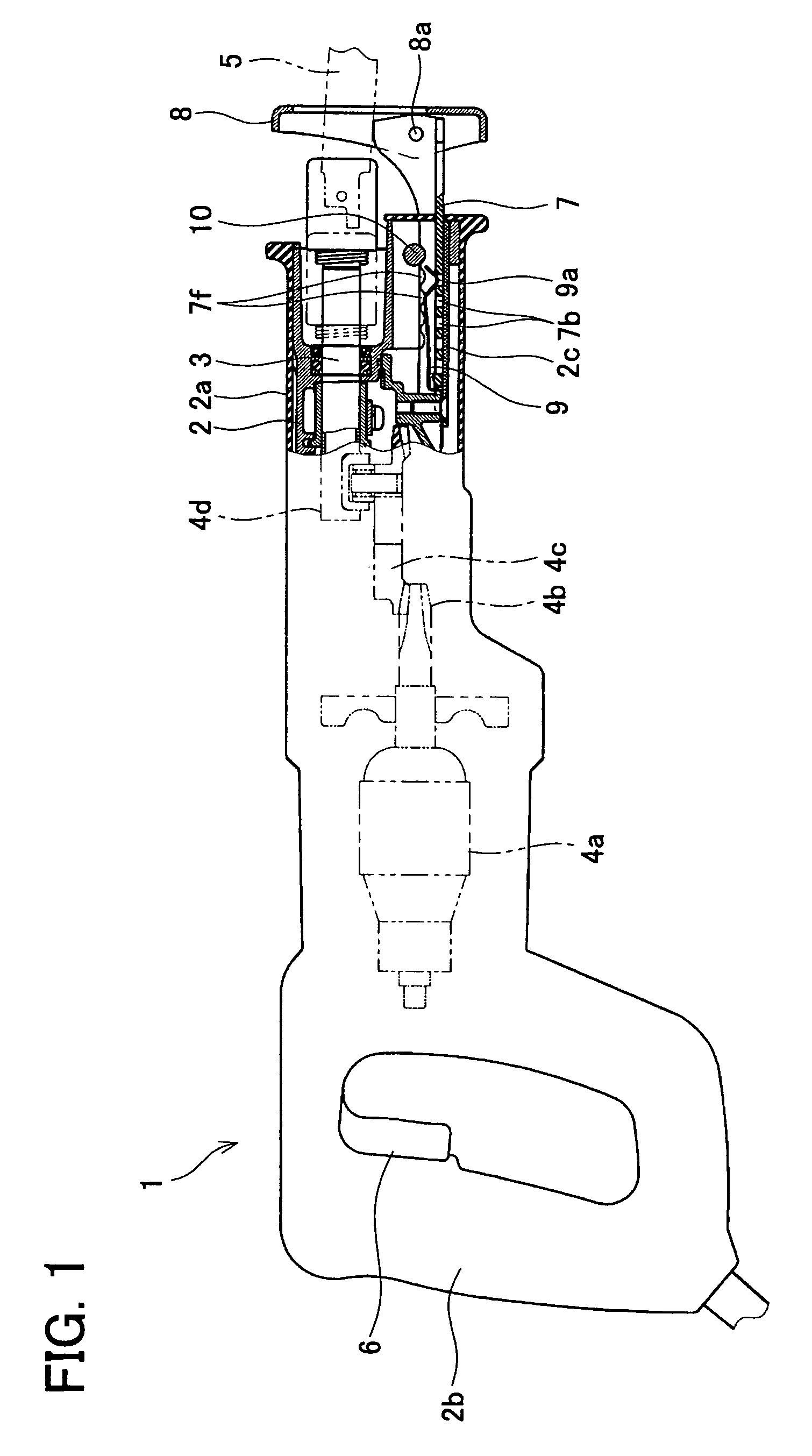
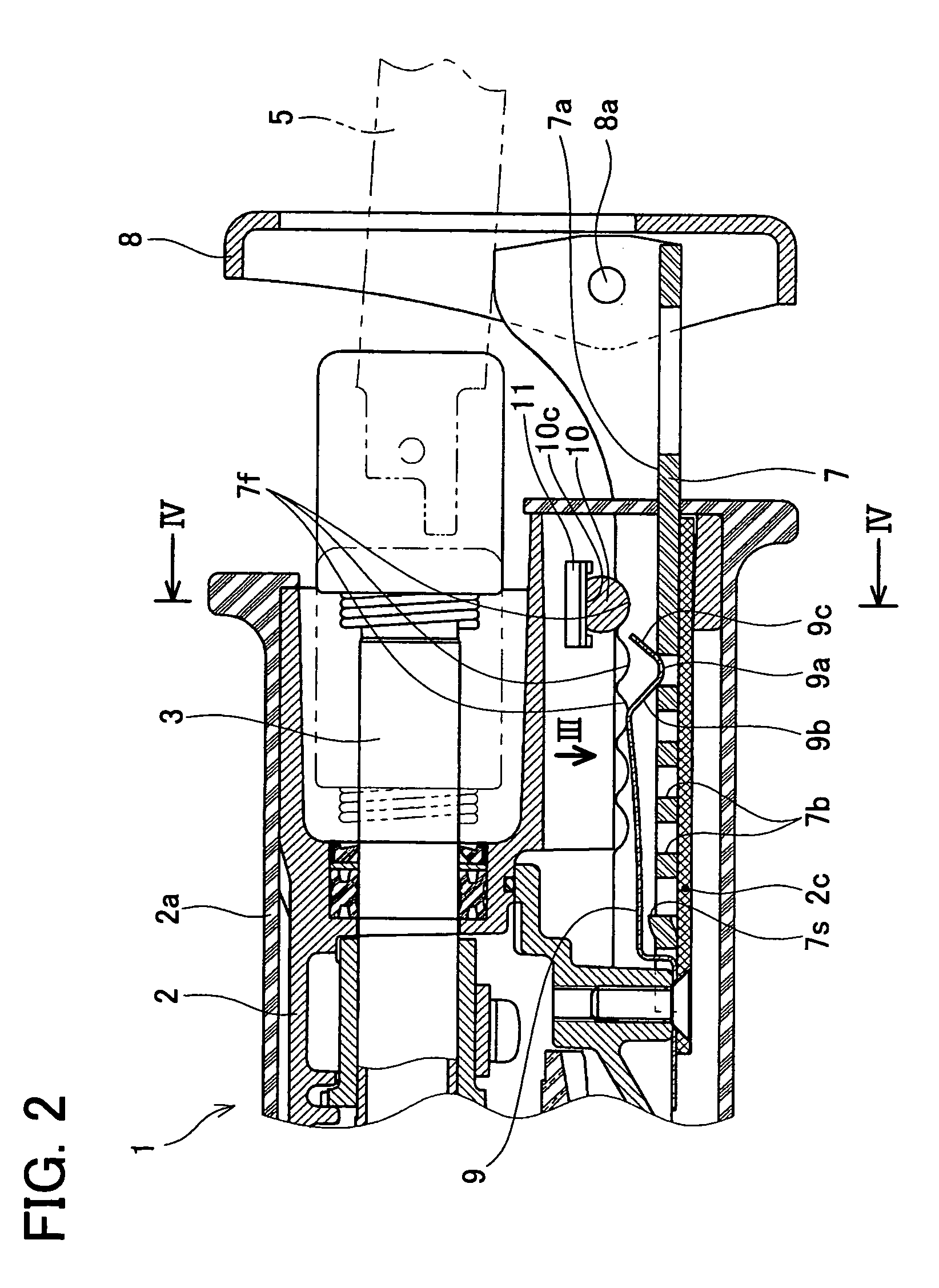
[0016]In this reciprocating saw, the operator slides the support member in order to adjust the location of the guide shoe. Thereupon, the engaging member and the support member engage, or release their engagement, as the support member passes across locations allowing locking or locations not allowing locking. The operator can recognize whether the support member is in a location allowing locking or in a location not allowing locking by means of minute oscillation, sound, or resistance occurring when the engaging member and the support member engage, or when their engagement is released. While the operator is adjusting the location of the guide shoe, the operator can recognize whether locking is possible or impossible in that location. It is no longer the case that the operator learns only after adjusting the guide shoe that the location chosen does not allow the guide shoe to be locked. Furthermore, the operator can lock the support member easily.
[0017]It is preferred that, after the engaging member and the support member have engaged, the engaging member prevents the release of their engagement by means of the weight of the support member. And it is preferred that release is performed in a simple manner by means of the operator exerting force to slide the support member. By adjusting the energizing force applied to the engaging member, a relationship can be realized in which the support member that is in the unlocked state is prevented from sliding freely due to its self-weight, while simultaneously it can be easily slid when the operator wishes to slide this support member.
[0022]The operator can lock the support member easily without incurring trouble in fixing the location of this support member.
[0023]According to the present teachings, it is possible to make it easier to fix the location of the support member that supports the guide shoe, and to perform the operation of locking the support member. The operator can adjust the location of the guide shoe simply and rapidly.

Problems solved by technology

While altering the location of the guide shoe, the operator cannot recognize whether the guide shoe is in a location that allows locking.
Only when attempting to lock the guide shoe after adjusting it to the desired location, the operator can discover that the guide shoe cannot be locked in this location.
Therefore, these reciprocating saws require that the operator carry out troublesome operations.

Method used


Image

  • Reciprocating saw
  • Reciprocating saw
  • Reciprocating saw

Examples


embodiment 2

[0045]A second embodiment of a reciprocating saw will be described. This presents a different configuration for an engaging part in the reciprocating saw 1 of Embodiment 1. As shown in FIG. 5, a plurality of engaging holes 17b are aligned in a support member 17. Upper end faces 17d of walls 17c between adjacent engaging holes 17b form upwardly-protruding curved convex faces. An engaging protrusion 9a of an engaging member 9 forms a downwardly-protruding curved convex face. As a result, when the engaging protrusion 9a makes contact with the upper end face 17d, engagement between the two is unstable irrespective of the location in which this contact occurs. Spring force of the engaging member 9 constantly energizes the support member 17 towards a stable location in which the engaging protrusion 9a enters the engaging hole 17b. By this means, the location of the support member 17 can be fixed more easily.

[0046]In the present embodiments, the engaging holes engaged with engaging member ...


PUM

PropertyMeasurementUnit
self-weightaaaaaaaaaa
lengthaaaaaaaaaa
energizing forceaaaaaaaaaa

Abstract

The reciprocating saw has a main body, a support member, a guide shoe, a locking member and an engaging member. The support member can be slid relative to the main body. The guide shoe is attached to an anterior end of the support member. The locking member can be switched between a state allowing the support member to be slid relative to the main body and a state not allowing the sliding. The engaging member is energized towards the support member. The engaging member and the support member engage or release their engagement, while the support member is being slid relative to the main body across a location allowing locking and a location not allowing locking.

Description

CROSS-REFERENCE[0001]This application claims priority to Japanese Patent Application No. 2004-48981, filed on Feb. 25, 2004, the entire contents of which are hereby incorporated by reference.BACKGROUND OF THE INVENTION[0002]1. Field of the Invention[0003]The present invention relates to reciprocating saws. Specifically, it relates to reciprocating saws improved in an operation for adjusting location of a guide shoe.[0004]2. Description of the Related Art[0005]Reciprocating saws are one type of power tools. A reciprocating saw comprises a guide shoe attached to the reciprocating saw's main body (hereafter referred to simply as main body). When an operator utilizes a reciprocating saw for cutting a work, the operator keeps the guide shoe in contact with the work in order to stabilize the main body.[0006]A reciprocating saw is constructed to be able to adjust the location of the guide shoe in a direction of reciprocating motion of a saw blade. By means of adjusting the location of the ...

Claims


Application Information

Patent Timeline
Patent Type & Authority Patents(United States)
IPC IPC(8): B27B11/02B23D51/02
CPCB23D51/02
Inventor SUGIURA, SHINYOSHIKANE, KIYONOBU
Owner MAKITA CORP
Learn More