
Method and device for control of a unit for reproduction of an acoustic field

a technology of reproduction unit and control device, which is applied in the direction of amplification control, stereophonic arrangments, electrical apparatus, etc., can solve the problems of inability to perform quality reproduction, inability to process spatial aspects in full, and inability to achieve quality reproduction

Active Publication Date: 2008-07-01
BRUNO +2
View PDF11 Cites 15 Cited by
  • Summary
  • Abstract
  • Description
  • Claims
  • Application Information

AI Technical Summary

Benefits of technology

[0022]a step of shaping said input signal by decomposing said information over a basis of spatio-temporal functions, this shaping step making it possible to deliver a representation of said acoustic field to be reproduced corresponding to said sound environment in the form of a linear combination of said functions;
[0045]the method comprises a calibration step making it possible to deliver all or part of the parameters used in said step of determining reconstruction filters;
[0064]the method comprises a step of input making it possible to determine all or part of the parameters used during said step of determining reconstruction filters;

Problems solved by technology

The existing techniques act mainly on the temporal aspect of sounds, the processing of the spatial aspect being very incomplete.
Thus, when the existing techniques are implemented with a reproduction unit whose spatial distribution is arbitrary, the quality of reproduction is greatly impaired, in particular on account of angular distortions.
No element makes it possible to ensure high-quality reproduction with the help of an arbitrary spatial configuration of the reproduction unit.
It is therefore apparent that no system of the prior art makes it possible to perform quality reproduction with the help of an arbitrary spatial configuration of the reproduction unit.

Method used


Image

  • Method and device for control of a unit for reproduction of an acoustic field
  • Method and device for control of a unit for reproduction of an acoustic field
  • Method and device for control of a unit for reproduction of an acoustic field

Examples


Embodiment Construction

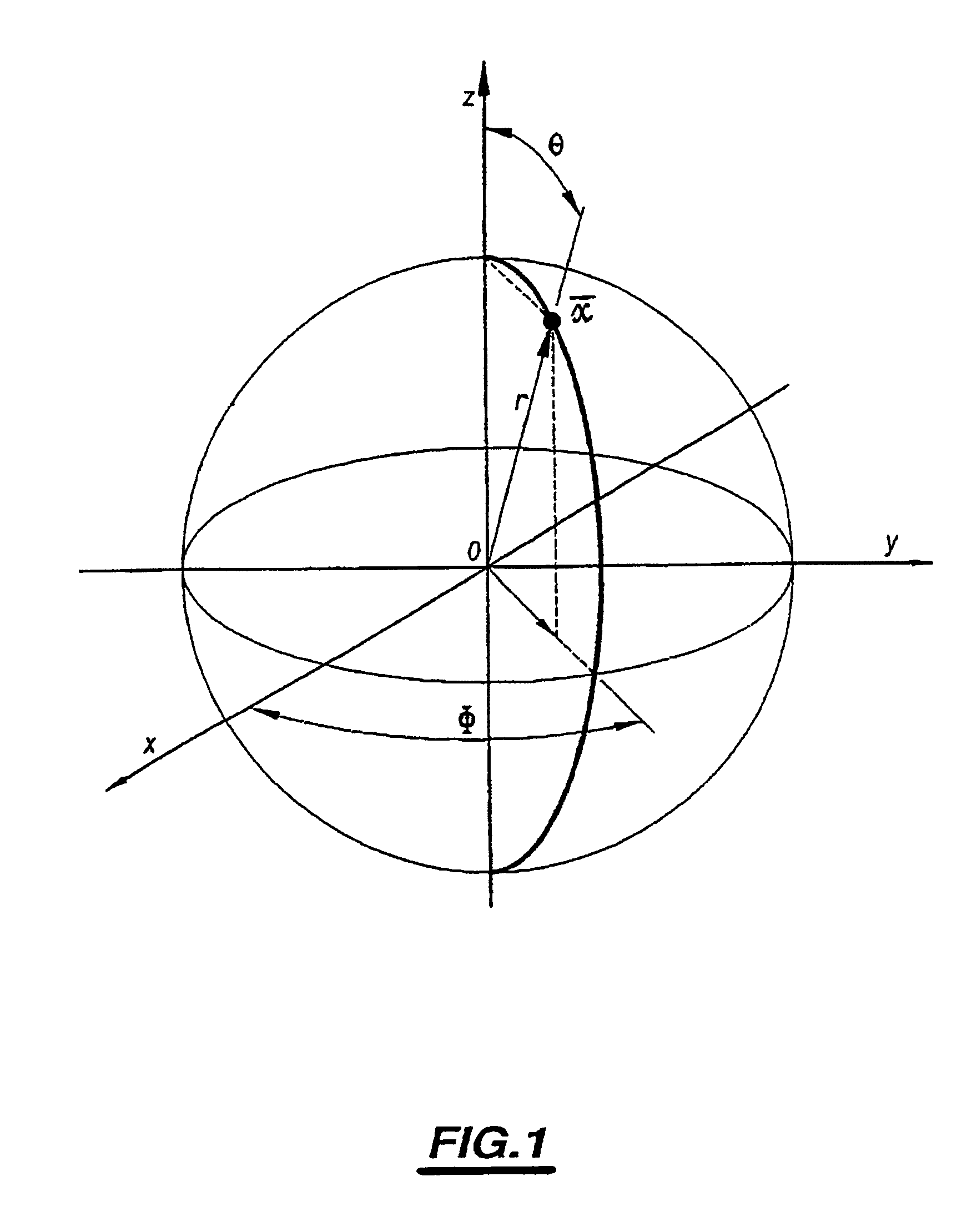
[0114]Represented in FIG. 1 in such a way as to specify the system of coordinates to which reference is made in the text is a conventional spherical reference frame.

[0115]This reference frame is an orthonormal reference frame, with origin O and comprising three axes (OX), (OY) and (OZ).

[0116]In this reference frame, a position denoted x is described by means of its spherical coordinates (r,θ,φ), where r designates the distance with respect to the origin O and θ the orientation in the vertical plane and φ the orientation in the horizontal plane.

[0117]In such a reference frame, an acoustic field is known if at each instant t the acoustic pressure denoted p(r,θ,φ,t), whose temporal Fourier transform is denoted P(r,θ,φ,f) where f designates the frequency, is defined at every point.

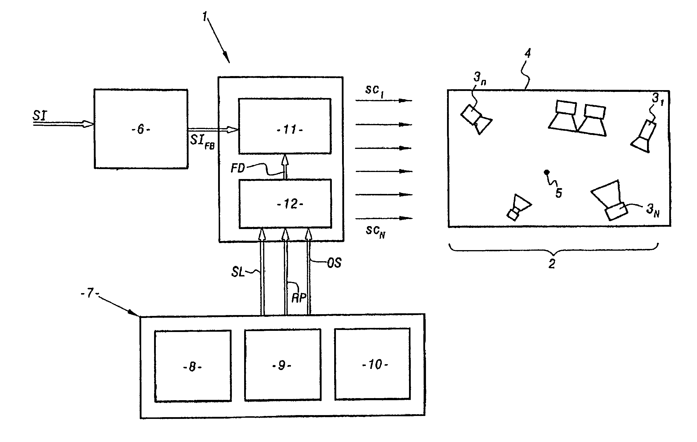
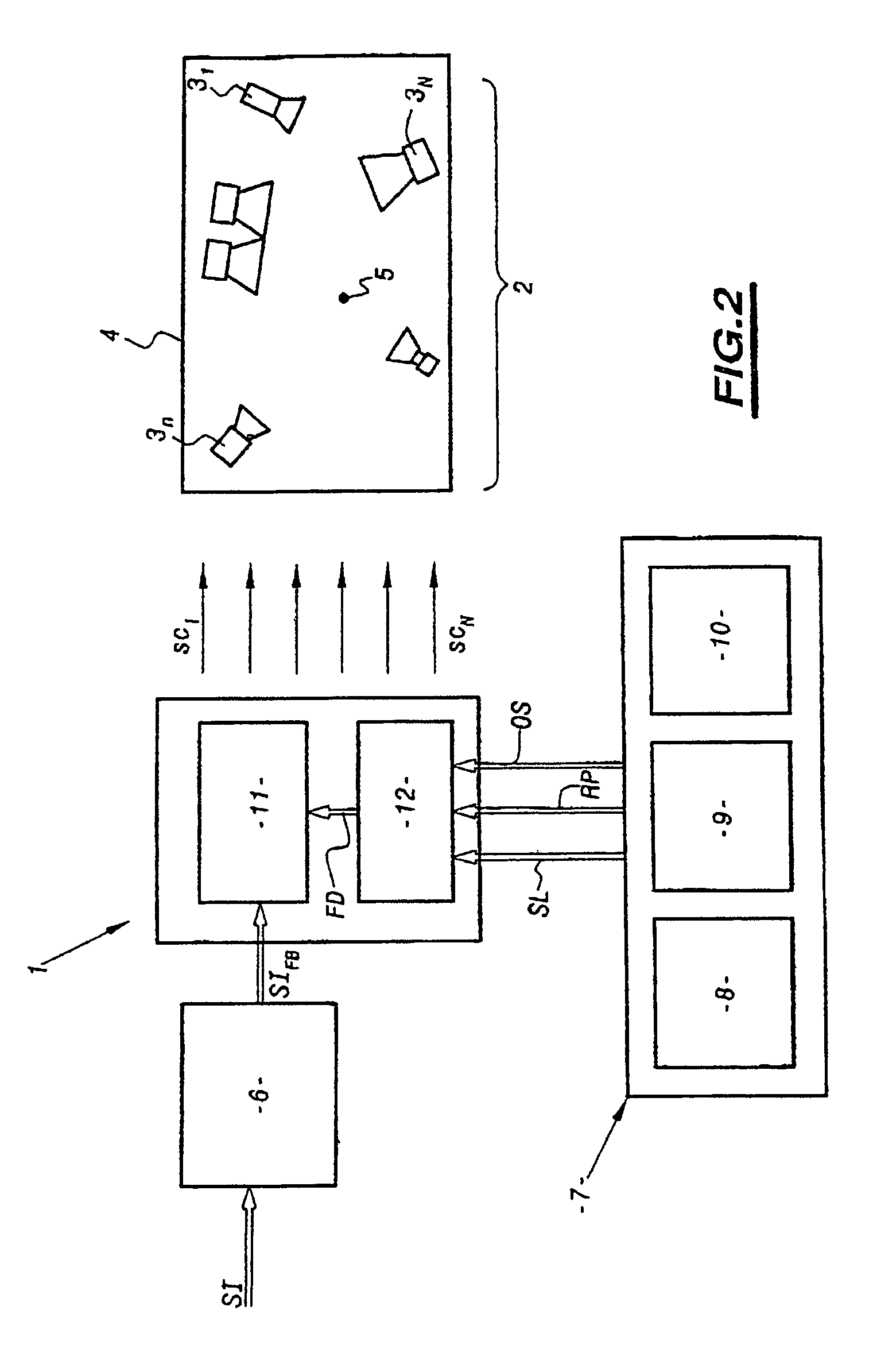
[0118]FIG. 2 is a representation of a reproduction system according to the invention.

[0119]This system comprises a decoder 1 controlling a reproduction unit 2 which comprises a plurality of elements 31 to 3N, ...


PUM


Abstract

Said method for control of a reproduction unit (2) for an acoustic field with a number of reproduction elements (31 to 3N) is characterised in comprising: a step for establishing a finite number of coefficients representative of the temporal distribution and in the three spatial dimensions of said acoustic field, a step for determination of representative reconstruction filters for said reproduction unit (2) and at least the spatial configuration of said reproduction unit (2); a step for determination of at least on control signal (SC1 to SCN) for said elements (31 to 3N) by the application of said coefficients to said reconstruction filters and a step for providing said at least one control signal for application to said elements (31 to 3N) for generation of said acoustic field for reproduction.

Description

BACKGROUND OF THE INVENTION[0001]The present invention relates to a method and a device for control of a reproduction unit for an acoustic field.DESCRIPTION OF THE RELATED ART[0002]Sound is a wavelike acoustic phenomenon which evolves over time and in space. The existing techniques act mainly on the temporal aspect of sounds, the processing of the spatial aspect being very incomplete.[0003]Specifically, the existing high-quality reproduction systems actually necessitate a predetermined spatial configuration of the reproduction unit.[0004]For example, so-called multichannel systems address different and predetermined signals to several loudspeakers whose distribution is fixed and known.[0005]Likewise, so-called “ambisonic” systems, which consider the direction from which the sounds which reach a listener originate, require a reproduction unit whose configuration must comply with certain positioning rules.[0006]In these systems, the sound environment is regarded as an angular distribu...

Claims


Application Information

Patent Timeline
Patent Type & Authority Patents(United States)
IPC IPC(8): H03G3/00H04S7/00H04S3/00H04S5/02
CPCH04S3/02H04S7/301H04S3/00
Inventor BRUNO, REMYLABORIE, ARNAUDMONTOYA, SEBASTIEN
Owner BRUNO
Learn More