Methods of joining structures and joints formed thereby

a technology of joining structure and joint, applied in the field of joining structure, can solve the problems of difference in materials required to form the joint, the weight of adhesion bonded joints is not necessarily lighter,

Active Publication Date: 2008-07-01
THE BOEING CO
View PDF7 Cites 61 Cited by
  • Summary
  • Abstract
  • Description
  • Claims
  • Application Information

AI Technical Summary

Problems solved by technology

Although adhesively bonded joints are not necessarily lighter than mechanically fastened joints, in many cases they are.
This difference often results from the difference in materials required to form the joints.

Method used


Image

  • Methods of joining structures and joints formed thereby
  • Methods of joining structures and joints formed thereby
  • Methods of joining structures and joints formed thereby

Examples


Embodiment Construction

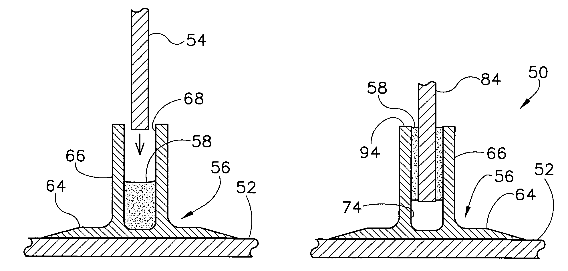
[0020]The present invention relates to a method of joining two or more structures, and more particularly to a method of joining two structures using an adhesively bonded joint having a cavity that is substantially free of adhesive. Referring now to the figures, and more particularly to FIG. 4, a joint according to a first embodiment of the present invention is designated in its entirety by reference number 50. The joint 50 connects a first structure 52 to a second structure 54 using a joint element 56 and an adhesive 58. The second structure 54 has faces 60 and a lower surface 62. The joint element 56 has a base 64 and two legs 66 extending from the base. The legs 66 define a slot 68 having opposing sides 70 and a bottom 72.

[0021]The bottom 72 of the slot 68, the sides 70 of the slot, the adhesive 58, and the lower surface 62 of the second structure 54 define a cavity 74 that is substantially free of adhesive 58. The cavity 74 can be kept free of adhesive 58 in a variety of ways. Th...


PUM

PropertyMeasurementUnit
electrically conductiveaaaaaaaaaa
modulus of elasticityaaaaaaaaaa
flexibleaaaaaaaaaa

Abstract

A method of joining a first structure to a second structure using a joint element. The joint element has a base and at least two legs extending from the base and the legs define a slot having opposing sides and a bottom. The method comprises attaching the joint element to the first structure and inserting the second structure into the slot. The method further includes injecting an adhesive into the slot. The method also includes ensuring a cavity is formed between the bottom of the slot and the second structure and the cavity is substantially free of adhesive.

Description

[0001]This invention was made with government support under a grant from the U.S. Air Force (F33615-98-3-5103). The U.S. government has certain rights in this invention.BACKGROUND OF THE INVENTION[0002]The present invention relates to a method of joining structures, and specifically a method of joining two structures using an adhesively bonded joint.[0003]A common method for connecting structures is by mechanical fastening. Mechanical fastening includes connecting a first structure 10 to a second structure 12 directly using mechanical fasteners 14, as shown in FIG. 1, or connecting the first structure 10 to a second structure 16 indirectly by way of one or more intermediate components 18 and mechanical fasteners 14, as shown in FIG. 2. Although mechanical fastening is often acceptable in terms of cost, weight, complexity and strength, fastening methods having still lower costs, complexity, and weight, without compromising strength, are always desired.[0004]One substitute for mechani...

Claims


Application Information

Patent Timeline
Patent Type & Authority Patents(United States)
IPC IPC(8): B29C45/14
CPCB29C65/527B29C65/562B29C66/43441B29C66/474B29C66/721F16B11/006B29C65/544B29C65/524B29C66/112B29C66/12441B29C66/131B29C65/7826B29C65/542Y10T428/24174B29C65/72B29K2063/00B29K2309/08B29C65/483Y10T428/28Y10T428/24182Y10T428/24198B29C66/7212B29C66/71B29K2307/04
Inventor GROSE, DOUGLAS L.WANTHAL, STEVEN P.SWEETIN, JOSEPH L.MATHIESEN, CHRISTOPHER B.SOUTHMAYD, RANDY A.
Owner THE BOEING CO
Why Eureka
Try Eureka