
Floor for an intercommunication bellows between two cars

a technology of intercommunication bellows and floor, which is applied in the direction of coupled vehicle gangways, railway bodies, transportation and packaging, etc., can solve the problem of not being able to optimize the distribution of displacemen

Active Publication Date: 2008-07-01
HUTCHINSON SA
View PDF6 Cites 14 Cited by
  • Summary
  • Abstract
  • Description
  • Claims
  • Application Information

AI Technical Summary

Benefits of technology

The invention provides a flexible floor for an intercommunication bellows between two cars that can follow the relative displacements of the cars as they are going around bends. The floor has transverse undulations reinforced by metal blades and elastomer reinforcements. The elastomer reinforcements are made up of at least two blocks that are spaced apart from the longitudinal plane symmetry of the floor. The floor also has elastomer reinforcements on either side of the transverse midplane, with the rank of each reinforcement increasing towards the longitudinal ends of the floor. The elastomer reinforcements may be interposed between metal elements and form a removable structure. The technical effect of the invention is to improve the flexibility and durability of the floor for intercommunication bellows.

Problems solved by technology

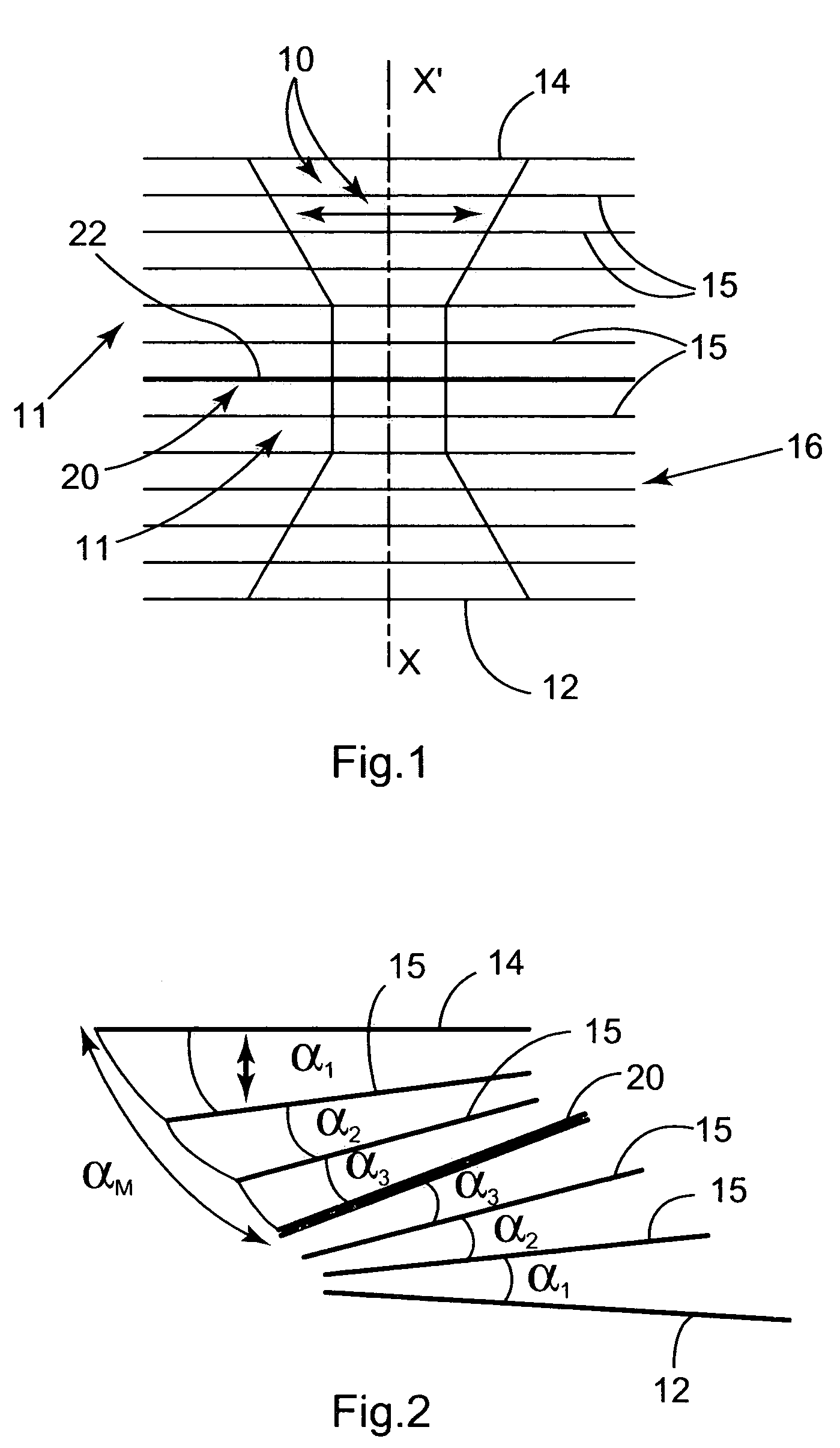
Such known reinforcements essentially suffer from the drawback of not making it possible to optimize the distribution of the displacements while the cars are moving in configurations corresponding to a tight bend followed by a bend back the other way, in which configurations the longitudinal axes of the cars remain parallel, but are offset transversely, with a fan-type deployment through a total pivot angle αM.

Method used


Image

  • Floor for an intercommunication bellows between two cars
  • Floor for an intercommunication bellows between two cars
  • Floor for an intercommunication bellows between two cars

Examples


Embodiment Construction

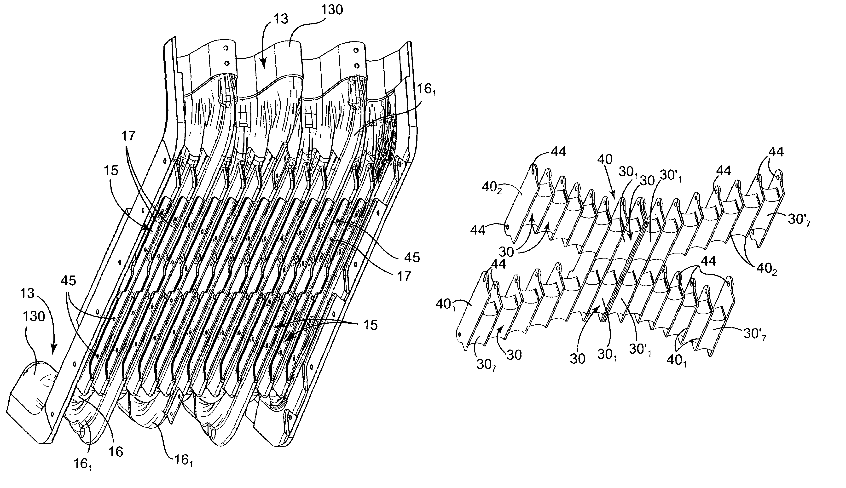
[0016]As shown in FIG. 1, a floor that is known, for example, from European Patent EP 860 305 is constituted by a solid piece of elastomer which is obtained by molding and which presents transverse undulations 16 provided with reinforcements constituted by metal blades 15. The undulations 16 are interrupted in a central region of the floor by solid elastomer reinforcements 10 of width L that is at its minimum in a middle region 11 and that increases progressively going towards the longitudinal ends 12 and 14 that are secured to the bodies of cars.

[0017]When there are two half floors, a central ring 22 exists in the midplane 20, and one end of each the two half-floors is secured to the end of the body of a respective car. They are identical and mounted head-to-tail, their other ends being secured to the central ring 22.

[0018]As shown in FIG. 2, in a configuration including a tight bend followed by a bend back the other way, the body edges of the two cars, and therefore the longitudin...


PUM


Abstract

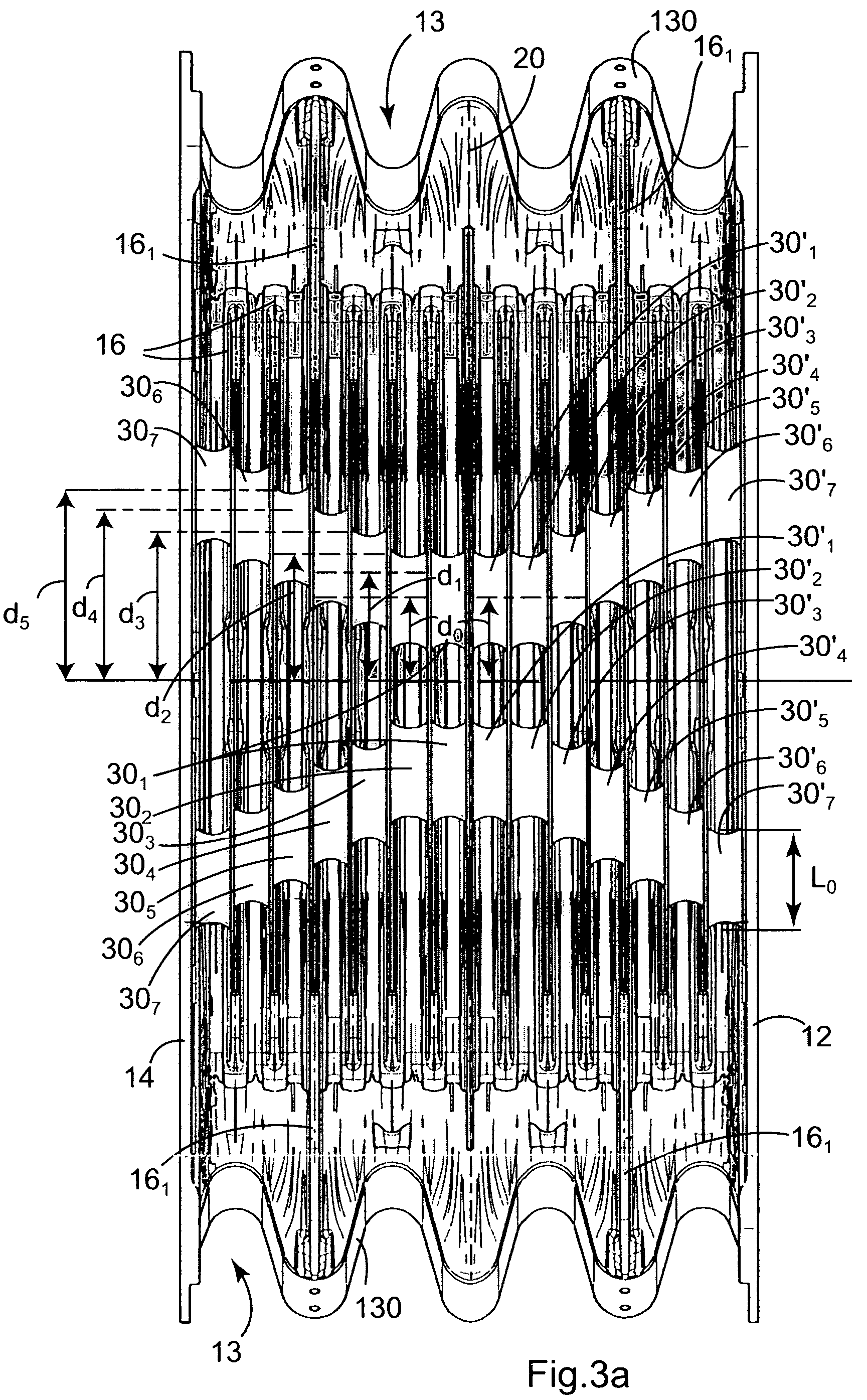
The invention relates to a flexible floor for an intercommunication bellows between two cars which, while they are traveling in a straight line, move in a longitudinal direction, said floor presenting transverse undulations enabling it to follow the relative displacements of said cars as they are going around bends, while also enabling passengers to go between the cars by walking on the top face of the floor, said transverse undulations being reinforced by metal blades extending in a transverse direction of the floor, and said floor being provided with an elastomer reinforcement interposed between the blades of each pair of said metal blades. In the floor, said elastomer reinforcements are of substantially the same transverse dimension 2L0, and each of them is constituted by at least one elastomer block, and, for at least one pair of metal blades adjacent to a longitudinal end of the floor, the elastomer reinforcement interposed between said metal blades is made up of at least two blocks which are spaced apart from the longitudinal plane symmetry of the floor, which plane is parallel to said longitudinal direction.

Description

[0001]The present invention relates to a flexible floor designed for an intercommunication corridor or gangway bellows between two cars, and more particularly designed for rail vehicles such as subway trains, trams, etc., or for articulated vehicles such as buses.BACKGROUND OF THE INVENTION[0002]Such a floor is known, for example, from European Patent EP 860 305 filed by Hutchinson on Feb. 16, 1998.[0003]Such a floor has transverse undulations which are reinforced by metal blades, and, in addition, the bottom portion of the floor is itself reinforced by interposing elastomer reinforcements which are disposed between the metal reinforcing blades in the central portion of the floor that constitutes a gangway zone. On the top face of the floor, or of the mat covering the floor, said gangway zone is plane and marked with tread in relief.[0004]Each gap between the blades thus receives a reinforcement of width that is at a minimum in the middle of the floor, and that increases progressive...

Claims


Application Information

Patent Timeline
Patent Type & Authority Patents(United States)
IPC IPC(8): B60D5/00B61D17/22B61D17/20
CPCB61D17/22B60D5/006H02J7/14
Inventor DE ANTONIO, RICHARDDALLE MOLLE, BRUNO
Owner HUTCHINSON SA
Learn More