
System and method for determining traffic conditions

a traffic condition and system technology, applied in the field of traffic conditions, can solve the problems of not immediately updating and delivering information, unable to provide an estimate of the travel time between two points on the route, and recurring problems

Inactive Publication Date: 2008-06-24
AMERICAN TELEPHONE & TELEGRAPH CO
View PDF10 Cites 25 Cited by
  • Summary
  • Abstract
  • Description
  • Claims
  • Application Information

AI Technical Summary

Benefits of technology

"The patent describes a method and system for using wireless devices to determine traffic conditions on selected routes. The system includes wireless devices in vehicles, a network for receiving signals from the devices, and a processor for counting the signals and comparing them with a predetermined value. The system can also determine the location of the vehicles and their velocity based on the signals. The traffic profile created by the system can be sent to the vehicles to help them avoid traffic congestion. The technical effect of this patent is to provide a more efficient and accurate way to determine traffic conditions on selected routes, which can help improve travel experiences for drivers and reduce traffic congestion."

Problems solved by technology

Various problems are encountered with this system.
One such problem is that information is not instantly updated and immediately delivered to the driver.
Also, it does not provide estimate travel time between two points on a route.
Moreover, it does not provide average vehicle speeds on other roadways or comparative roadway traffic information to the drivers to choose alternate routes, etc.
However, such systems provide velocity of all vehicles on the selected routes regardless of whether these vehicles are located on a completely empty road or in heavy traffic or in a zone where traffic has been disrupted due to construction on the road or due to a recent accident on the road.

Method used


Image

  • System and method for determining traffic conditions
  • System and method for determining traffic conditions
  • System and method for determining traffic conditions

Examples


Embodiment Construction

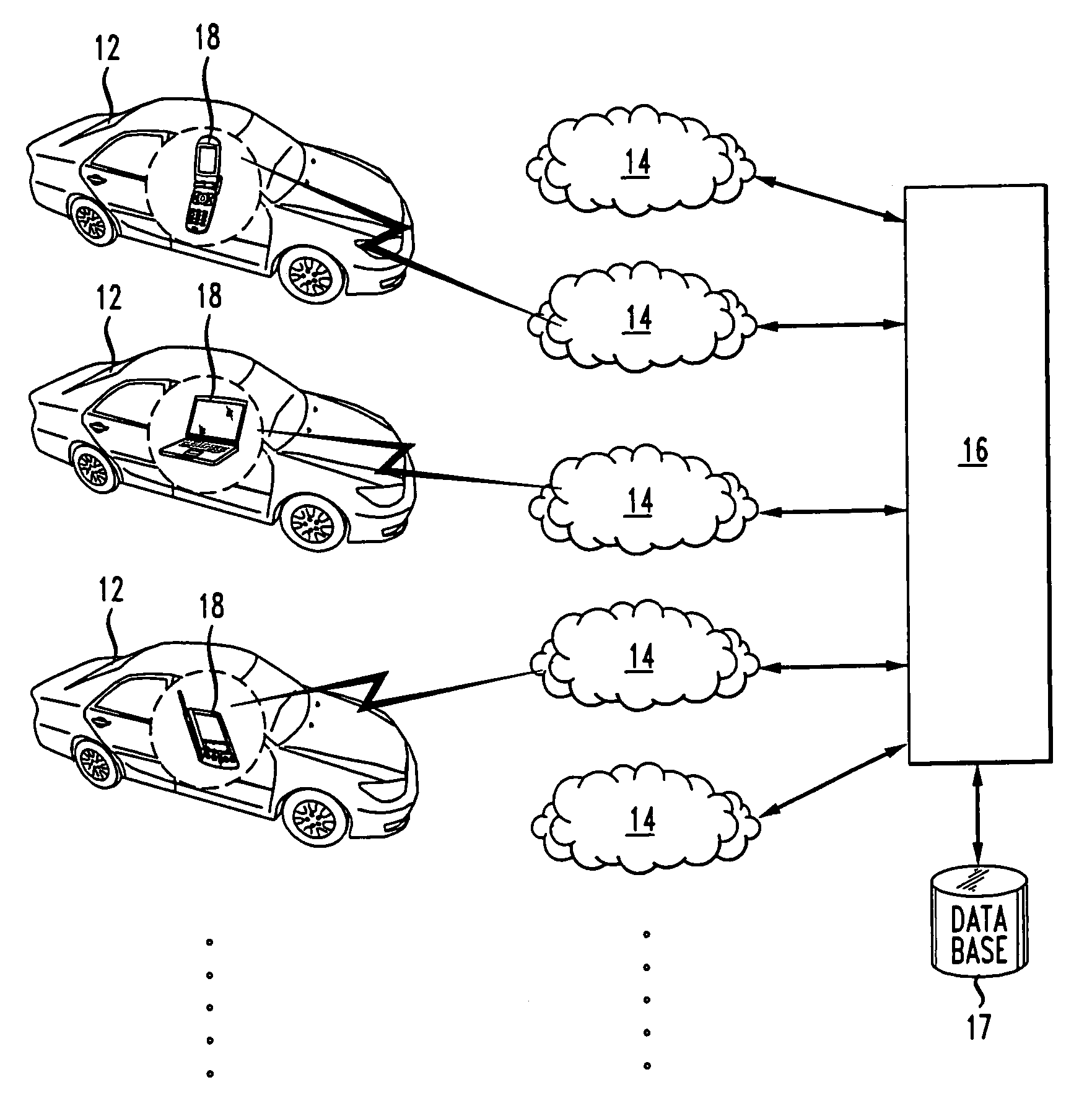
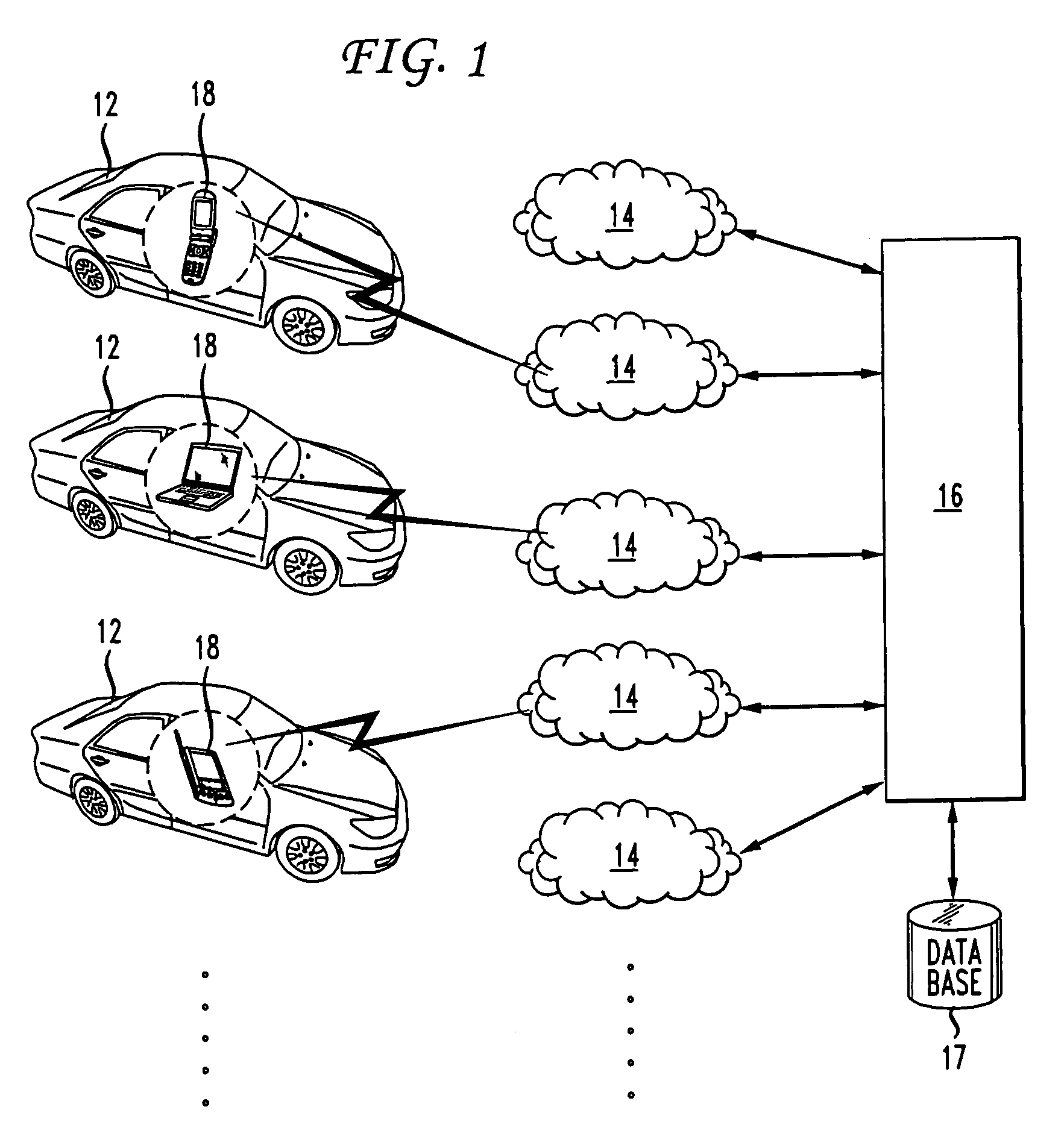
[0010]With reference to FIG. 1, there is shown an illustrative block diagram of a traffic determining system 10 according to an embodiment of the present invention. The system 10 includes a plurality of moving vehicles 12, each of them being capable of communicating with a central computer 16 via several wireless communication networks 14. Each of the moving vehicles 12 includes a wireless device 18 capable of transmitting its signals to the wireless communication network 14. The wireless device 18 may preferably be a wireless phone, a wireless lap-top computer, a wireless PDA, or a wireless on-board computer coupled to the wireless communication network 14. Each of the networks 14 includes base stations (not shown) which receive the signals from the wireless devices 18 whether or not they are making a call. The base stations in the network 14 communicate back and forth with the wireless devices 18. Each of networks 14 using each of their base stations are monitoring and instantaneo...


PUM


Abstract

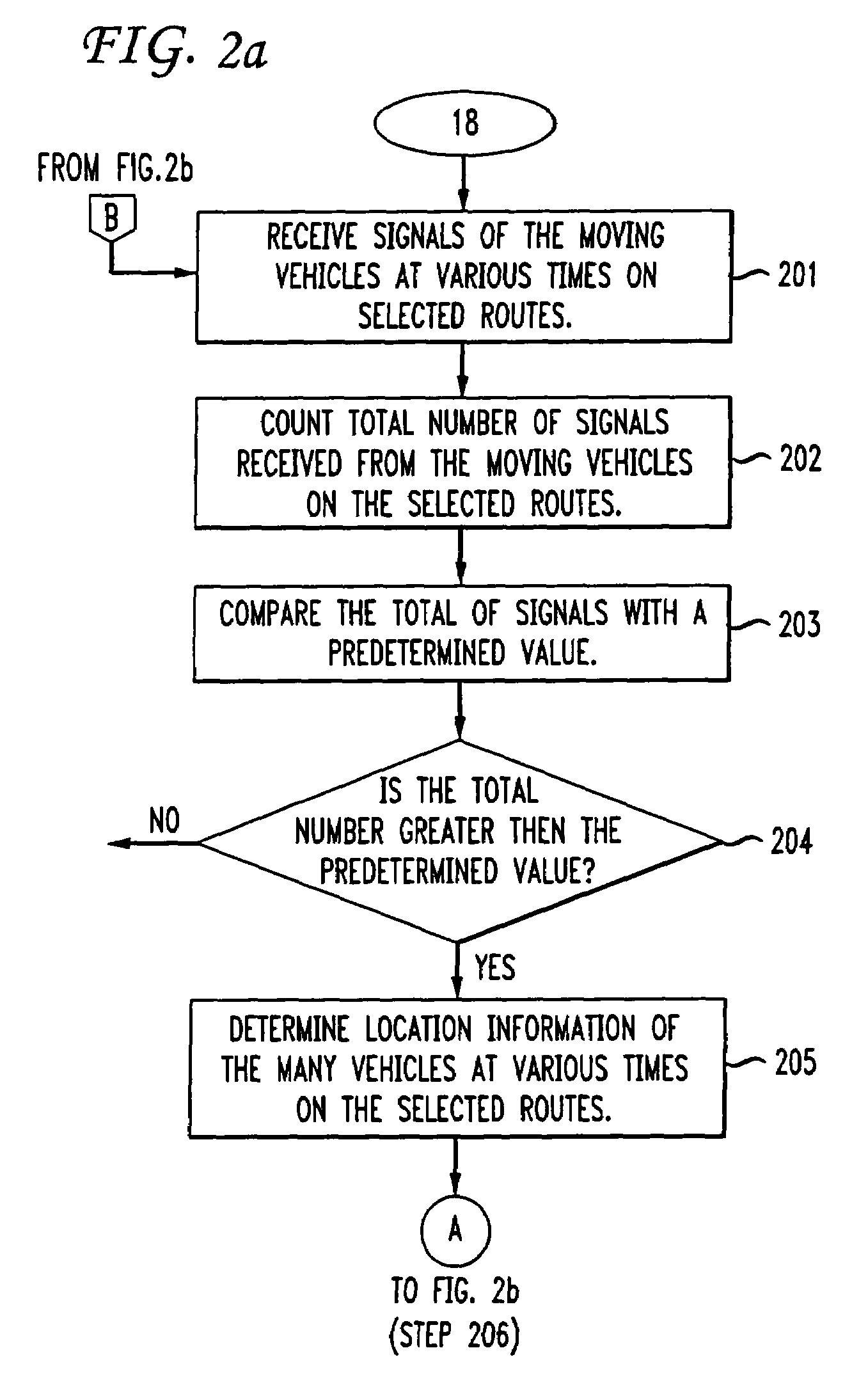
The present invention provides a method and apparatus for determining traffic conditions using wireless devices. A number of signals from the vehicles traveling in selected routes are received by several wireless communication networks via the wireless devices. The total number of signals received are used to compare if there are sufficient number of vehicles traveling on the selected routes. If so, then the location information of the moving vehicles at various times is determined by the wireless communication network and forwarded to a central computer. The central computer coordinates with the wireless communications network for information needed to compute traffic data. The central computer computes the velocity of the moving vehicles and a traffic profile is created based on the velocity and location information of the moving vehicles. Furthermore, the traffic profile is sent to the moving vehicles.

Description

CROSS-REFERENCE TO RELATED APPLICATIONS[0001]This application is a divisional of U.S. patent application Ser. No. 10 / 749,109 filed on Dec. 29, 2003, now U.S. Pat. No. 7,228,224 which is incorporated herein by reference.FIELD OF THE INVENTION[0002]The invention relates to the field of traffic conditions, and more particularly to method and apparatus for determining traffic conditions by tracking the locations of wireless devices in moving vehicles.BACKGROUND OF THE INVENTION[0003]Current systems for monitoring traffic conditions are based on observing vehicles directly with the use of video cameras installed on the poles. Traffic is observed by individuals and broadcast to the drivers via televisions or radios. Various problems are encountered with this system. One such problem is that information is not instantly updated and immediately delivered to the driver. Also, it does not provide estimate travel time between two points on a route. Moreover, it does not provide average vehicle...

Claims


Application Information

Patent Timeline
Patent Type & Authority Patents(United States)
IPC IPC(8): G06F19/00
CPCG08G1/20
Inventor ROSEN, KENNETH H.BANSAL, PRADEEP K.BANKS, DIANEBLEWETT, CHARLES DOUGLASROCK, TIMOTHY A.
Owner AMERICAN TELEPHONE & TELEGRAPH CO
Learn More