
Assembly used for cooling a circuit board or similar

a circuit board and cooling air technology, applied in electrical apparatus, electrical apparatus, liquid fuel engines, etc., can solve the problems of inability to use the area on which such a fan is installed, poor cooling air flow generated by usual miniature fans, etc., and achieve the effect of easy installation

Inactive Publication Date: 2008-06-24
EBM PAPST ST GEORGEN & -
View PDF17 Cites 43 Cited by
  • Summary
  • Abstract
  • Description
  • Claims
  • Application Information

AI Technical Summary

Benefits of technology

[0008]Another manner of achieving the stated object is to employ a carrier frame shaped like an offshore oil drilling ring, having a platform configured with a depression for installation of the cooling fan. A carrier frame of this kind can be installed easily and in foolproof fashion, and is mounted in very stable fashion on the circuit board after being installed.

Problems solved by technology

A disadvantage in this context is that the area on which such a fan is installed is no longer available for components, as indicated by DE 195 03 521 A1, AMRHEIN et al.
It is also disadvantageous that the cooling air flow generated by usual miniature fans is poorly suited, because of its shape, for direct cooling close to the surface on circuit boards.

Method used


Image

  • Assembly used for cooling a circuit board or similar
  • Assembly used for cooling a circuit board or similar
  • Assembly used for cooling a circuit board or similar

Examples


Embodiment Construction

[0021]Identical reference characters in the Figures designate identical or identically functioning elements. Terms such as “above,”“below,”“left,” and “right” refer to the respective Figure.

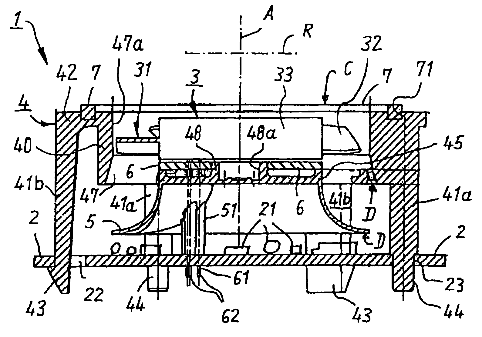
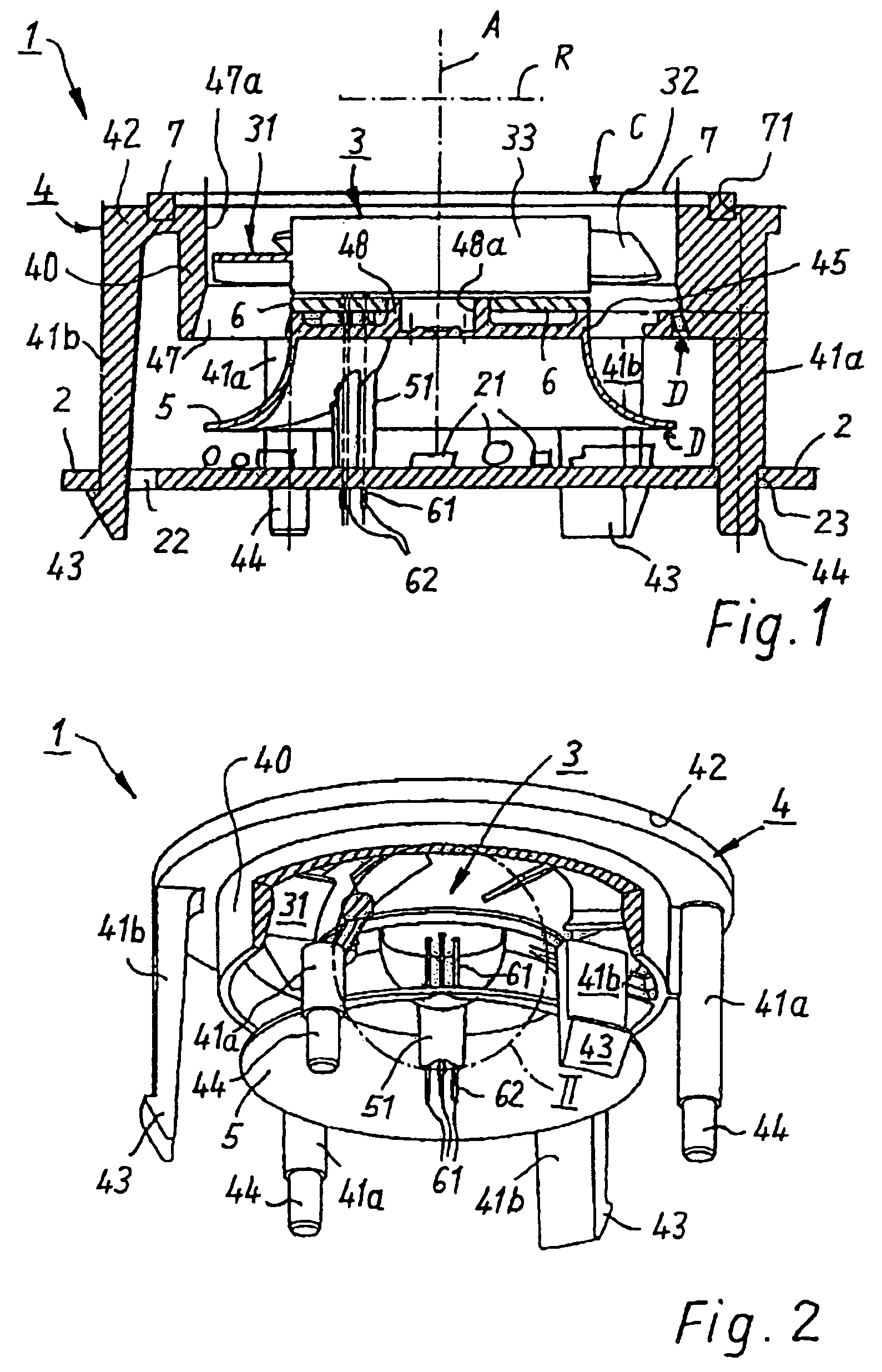
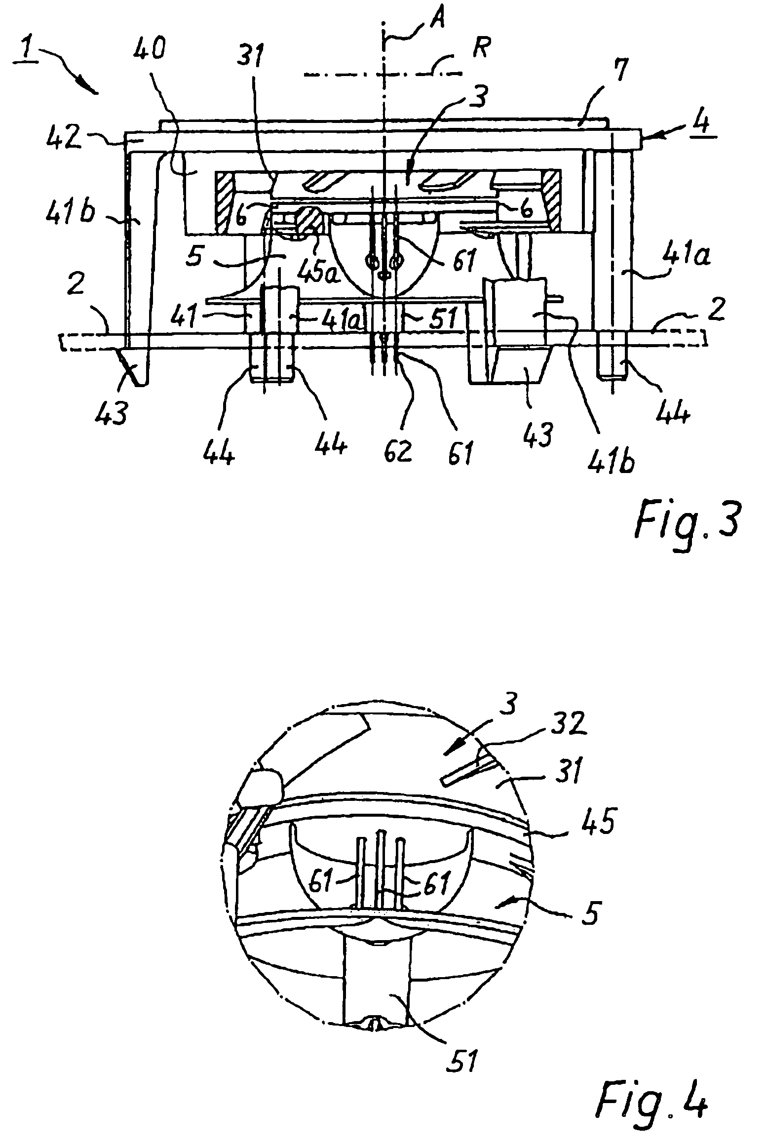
[0022]FIG. 1 is a schematic longitudinal section through an arrangement 1 according to the present invention. That arrangement has as its principal constituents a fan 3 having a fan wheel 31 whose fan blades are depicted at 32, and having an electric motor 33 to drive fan wheel 31. Arrangement 1 furthermore has a carrier frame 4 which carries fan 3 and on which the latter is mounted. Support elements 41a and latching elements 41b are shaped onto carrier frame 4. By means of latching elements 41b, carrier frame 4 can be mounted on a circuit board 2 by being clipped in. Components 21 that are to be cooled are depicted schematically on circuit board 2. FIG. 8 shows an alternative, preferred manner of mounting onto circuit board 2.

[0023]Fan 3 is arranged, with its fan wheel 31, in such a way that on ...


PUM


Abstract

A carrier frame (104), for installation on a circuit board (2), is implemented in the manner of an oil-drilling rig and comprises a platform (117) that is equipped with supporting legs (105, 106, 107, 108) for mounting on the circuit board (2). The carrier frame has, at the center of its platform (117), a depression (121, 123) that is implemented for installation of a fan (3) at a distance from the circuit board (2), the outer wall (123) of the depression (121, 123) forming part of the fan.

Description

CROSS-REFERENCE[0001]This application is a section 371 of PCT / EP2005 / 010652 filed 4 OCT. 2005.FIELD OF THE INVENTION[0002]The invention relates to an arrangement for cooling a circuit board or the like.BACKGROUND[0003]It is known to cool directly, by means of miniature and subminiature fans, regions of a circuit board at which a great deal of heat is generated. Such regions are usually referred to as “hot spots.”[0004]A disadvantage in this context is that the area on which such a fan is installed is no longer available for components, as indicated by DE 195 03 521 A1, AMRHEIN et al. It is also disadvantageous that the cooling air flow generated by usual miniature fans is poorly suited, because of its shape, for direct cooling close to the surface on circuit boards.SUMMARY OF THE INVENTION[0005]It is therefore an object of the invention to furnish a new arrangement for cooling a circuit board or the like.[0006]According to the invention, this object is achieved by an arrangement inc...

Claims


Application Information

Patent Timeline
IPC IPC(8): F04B17/03H05K7/20
CPCF04D19/002F04D25/0613F04D29/541F04D29/601F04D25/0693
Inventor WINKLER, WOLFGANG ARNO
Owner EBM PAPST ST GEORGEN & -
Learn More