
Advanced power management for computer displays

a power management and computer technology, applied in the field of advanced power management for computer displays, can solve the problems of increasing the backlight level, limiting the power consumption of the display, and user's ability to only adjust the backlight level so much, so as to achieve the effect of more display capability and less power consumption

Active Publication Date: 2008-06-17
MICROSOFT TECH LICENSING LLC
View PDF10 Cites 63 Cited by
  • Summary
  • Abstract
  • Description
  • Claims
  • Application Information

AI Technical Summary

Benefits of technology

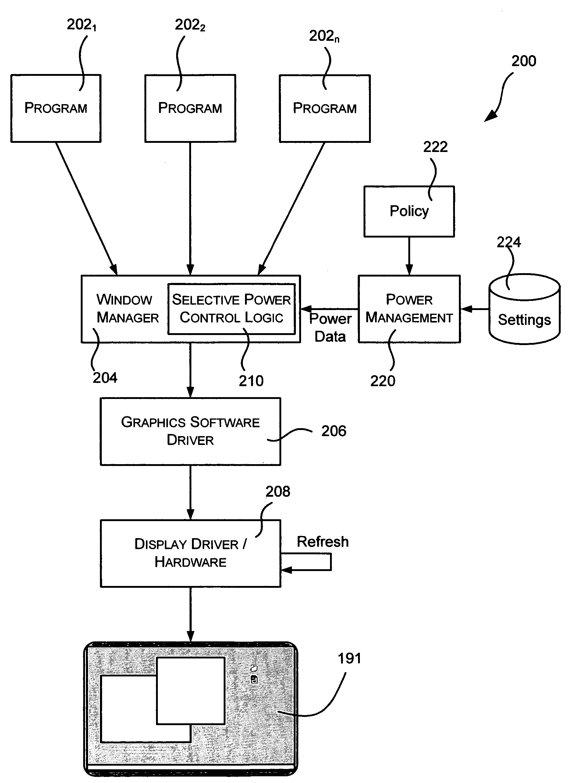
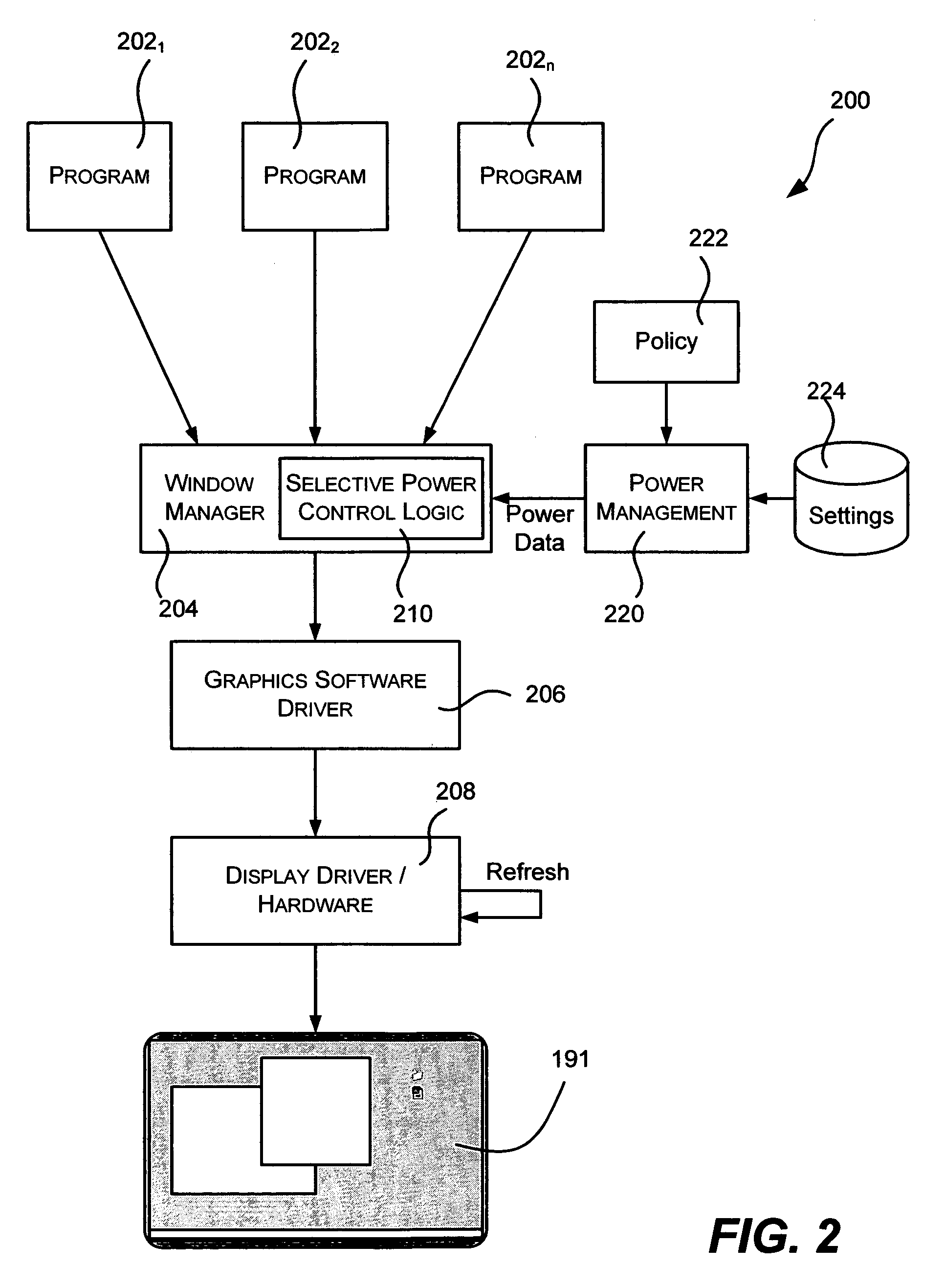
The present invention provides a system and method for managing the power of mobile displays by selectively controlling the power consumed by individual areas of the screen. This is done by using new display technologies, such as electroluminescent displays, that allow for individual control of pixels. The operating system can adjust the color levels, resolution, brightness, and on / off state of pixels to reduce power consumption. The system can also control the refresh rate and the backlight intensity of different areas of the display. Overall, this technology allows for more efficient use of power and improved user experience.

Problems solved by technology

The display on a mobile personal computer (PC) is one of the significant areas of power consumption, however the ability to control the power consumed by the display has heretofore been limited.
However, the user can only adjust the backlight level so much, based on the current surrounding environment, and the inactivity timer does not apply when the user is working on the computing device.
However, even when running with a reduced power profile, when the device is in use the inactivity timer is irrelevant, and the user has to tolerate the lowered backlight level to conserve power, or if not able to because of the current environment, raise the backlight level but then lose the power savings.

Method used


Image

  • Advanced power management for computer displays
  • Advanced power management for computer displays
  • Advanced power management for computer displays

Examples


Embodiment Construction

Exemplary Operating Environment

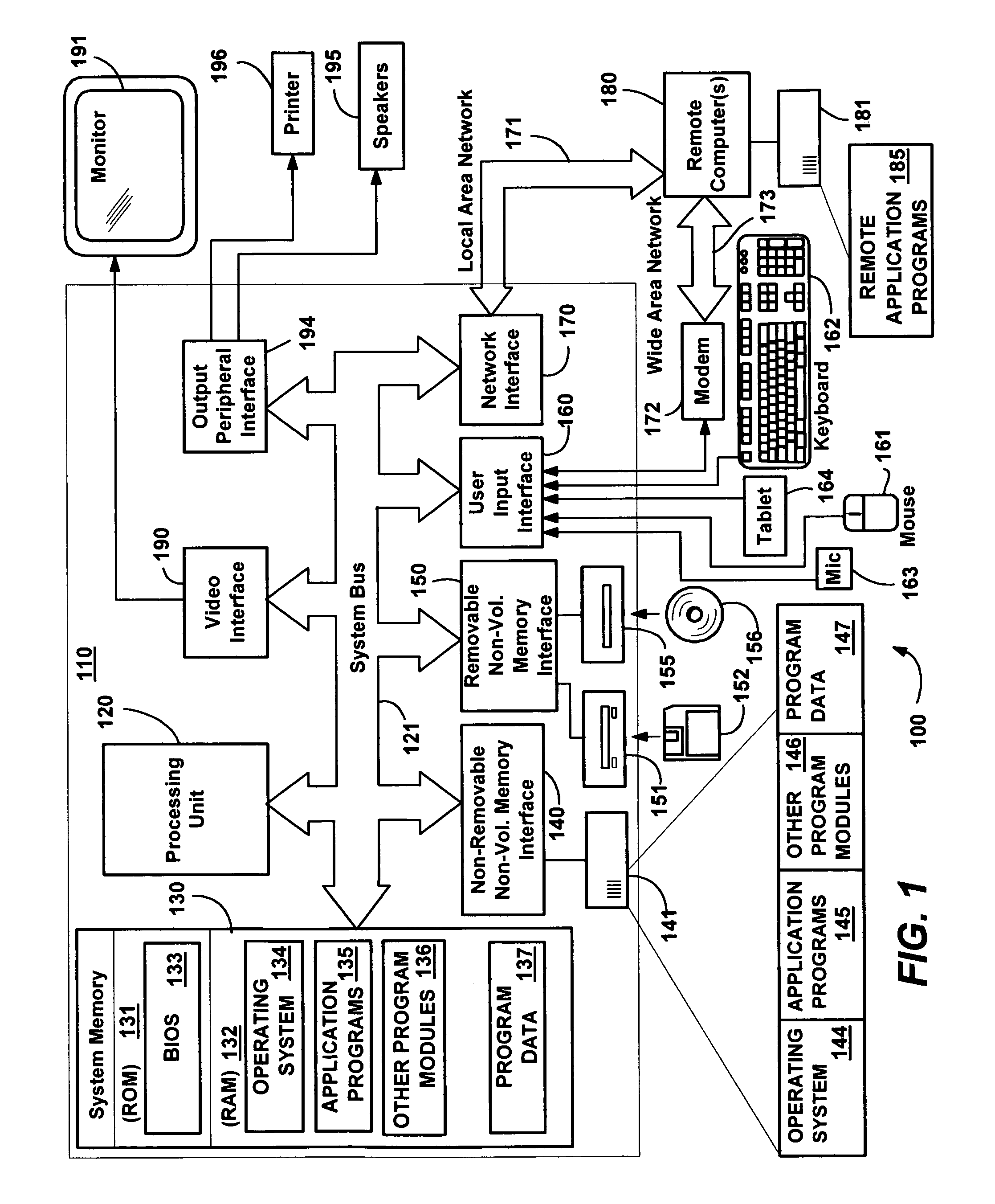
[0017]FIG. 1 illustrates an example of a suitable computing system environment 100 on which the invention may be implemented. The computing system environment 100 is only one example of a suitable computing environment and is not intended to suggest any limitation as to the scope of use or functionality of the invention. Neither should the computing environment 100 be interpreted as having any dependency or requirement relating to any one or combination of components illustrated in the exemplary operating environment 100.

[0018]The invention is operational with numerous other general purpose or special purpose computing system environments or configurations. Examples of well known computing systems, environments, and / or configurations that may be suitable for use with the invention include, but are not limited to: personal computers, server computers, hand-held or laptop devices, tablet devices, multiprocessor systems, microprocessor-based systems, set ...


PUM


Abstract

Described is a method and system for power management of mobile computer displays, in which areas of the screen are selectively controlled to consume less power than other areas. For example, a foreground window having focus may receive normal brightness, while background areas are dimmed. To this end, the pixels of selected areas are controlled to vary color depth, resolution, refresh rate, brightness and / or the on / off state for any part of the display. Power settings for parts of the display not corresponding to a focused window can be gradually reduced over time. Power policy may determine which areas are given reduced power, and external mechanisms provide information useful in the determination, such as when the user last interacted with a window, where the mouse is hovering, explicit user instructions as to how to power manage a window, and sensors that detect where the user is likely to want more power.

Description

FIELD OF THE INVENTION[0001]The invention relates generally to computer systems, and more particularly to controlling displays on a mobile computer system to save power.BACKGROUND OF THE INVENTION[0002]One of the fastest growing markets in contemporary computing is in mobile computing devices, such as laptop computers. When selecting a mobile computing device, many consumers consider the weight and battery life to be very important criteria. To an extent, the weight and battery life are traded off; e.g., the larger the device, the larger the battery that is needed to power it, and more than one battery is often carried with the device to prolong its usability between recharges.[0003]In general, when choosing a mobile device, the more efficient the power management, the longer the battery life will be relative to overall weight and / or system performance. As a result, device manufacturers are continually seeking ways to more efficiently manage power consumption.[0004]The display on a ...

Claims


Application Information

Patent Timeline
Patent Type & Authority Patents(United States)
IPC IPC(8): G06F1/26G06F1/32G06F3/038G06G5/00
CPCG06F1/3203G06F1/3265G09G2320/0626G09G2330/021Y02B60/1242Y02D10/00
Inventor CHANDLEY, ADRIANSCHOPPA, CHRISTOPHER A.NICHOLSON, CLARK D.
Owner MICROSOFT TECH LICENSING LLC
Learn More