
Method for determining a stuck point for pipe, and free point logging tool

a technology of free point logging and pipe, which is applied in the field of apparatus and methods for use in wellbores, can solve the problems of subterranean rock cavening into the bore and encasing the drill string, all drilling operations must be stopped, and the drill string can become bound or otherwise stuck

Inactive Publication Date: 2008-06-17
WEATHERFORD TECH HLDG LLC
View PDF46 Cites 57 Cited by
  • Summary
  • Abstract
  • Description
  • Claims
  • Application Information

AI Technical Summary

Problems solved by technology

Because of the non-linear path through the wellbore, the drill string can become bound or other wise stuck in the wellbore as it moves axially or rotationally.
In addition, the process of circulating fluids up the annulus within the earth formation can cause subterranean rock to cave into the bore and encase the drill string.
All drilling operations must be stopped and valuable rig time lost while the pipe is retrieved.
Mechanical free point tools of this type are considered reliable; however, they suffer from certain disadvantages.
In addition, mechanical free point tools are considered slow to operate.
In this respect, the sequential attachment and detachment of the free point tool to the drill string requires time.
Those familiar with the drilling industry understand that the operation of a drilling rig, particularly those located offshore, is very expensive.
However, the operation of such a tool remains expensive, as it requires that an electrical wireline be provided for running into the wellbore.

Method used


Image

  • Method for determining a stuck point for pipe, and free point logging tool
  • Method for determining a stuck point for pipe, and free point logging tool
  • Method for determining a stuck point for pipe, and free point logging tool

Examples


Embodiment Construction

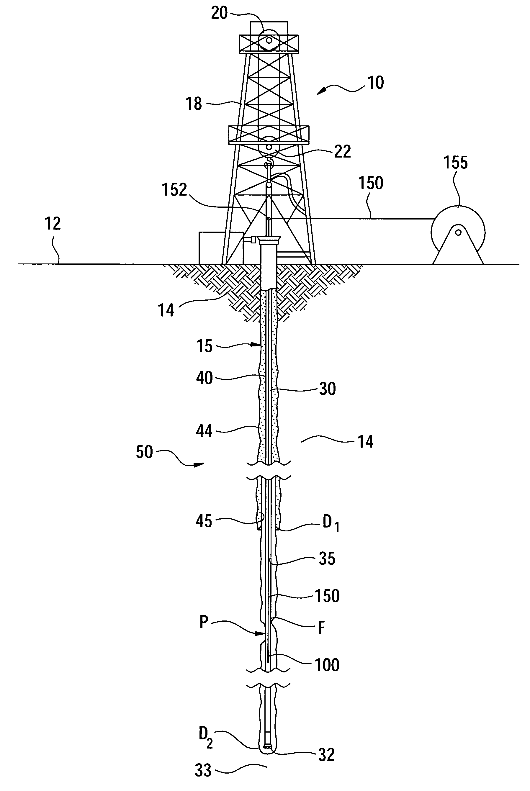
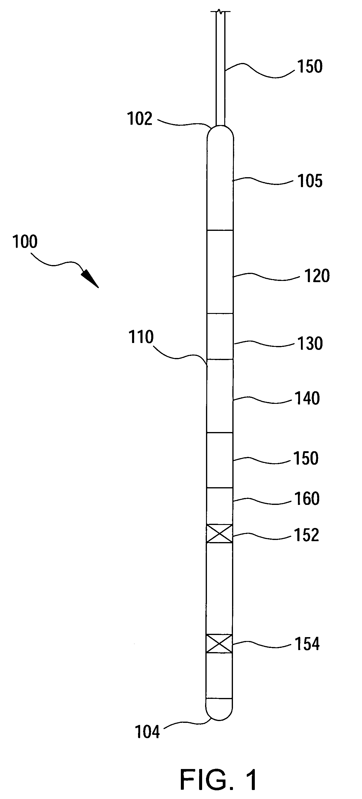
[0025]FIG. 1 provides a schematic side view of a free point logging tool 100, in one embodiment. This embodiment is configured to be run into a wellbore (such as wellbore 50 of FIG. 3) on a slickline. A slickline is shown in FIG. 1 at 150. For purposes of this disclosure, the term “slickline” also includes a sand line. The slickline provides mechanical connection between the tool 100 in the wellbore and a spool (such as spool 155 in FIG. 3) at the surface, but does not provide an electrical connection.

[0026]Other forms of mechanical connection between the tool 100 and a surface dispenser may also be employed. Such examples include tubing, coiled tubing and continuous sucker rods. For purposes of the disclosure herein, the line of FIG. 1 will be referred to as a slickline. Slickline is preferred due to its lower cost and efficiency.

[0027]The logging tool 100 includes a cable head 105 at an upper end 102 of the tool 100 for attaching to the slickline 150 during logging operations. In ...


PUM


Abstract

A method and apparatus for determining the location of stuck pipe are provided. In one embodiment, the method includes the step of attaching a free point logging tool to a working line such as a slickline or wireline. The free point logging tool has a freepoint sensor and, optionally, an acoustic sensor. The freepoint sensor acquires magnetic permeability data in a string of pipe, while the acoustic sensor acquires acoustic data in the pipe. Two sets of data for each sensor are acquired—one in which the pipe under investigation is unstressed, and one in which the pipe is stressed. The first set and second sets of magnetic permeability data are compared to determine the stuck point location for the pipe. The first and second sets of acoustic data are compared to determine the nature in which the pipe is stuck.

Description

CROSS REFERENCE TO RELATED APPLICATIONS[0001]This application is a continuation-in-part of U.S. patent application Ser. No. 10 / 211,252 filed Aug. 2, 2002 now U.S. Pat. No. 6,851,476, which claims benefit of U.S. Provisional Patent Application Ser. No. 60 / 310,124, filed Aug. 3, 2001.BACKGROUND OF THE INVENTION[0002]1. Field of the Invention[0003]The present invention relates to an apparatus and method for use in a wellbore. In addition, the invention relates to a downhole tool for determining the location and nature of an obstruction in a wellbore. More particularly still, the invention relates to a downhole tool for locating the point at which a tubular such as a drill string is stuck in a hollow tubular or a wellbore.[0004]2. Description of the Related Art[0005]Wellbores are typically formed by boring a hole into the earth through use of a drill bit disposed at the end of a tubular string. Most commonly, the tubular string is a series of threadedly connected drill collars. Weight i...

Claims


Application Information

Patent Timeline
Patent Type & Authority Patents(United States)
IPC IPC(8): G01V1/40E21B47/00E21B47/09G01V9/00
CPCE21B47/09E21B47/0905E21B47/091E21B47/095E21B47/092
Inventor GRAY, KEVIN L.
Owner WEATHERFORD TECH HLDG LLC
Learn More