
Liquid developing unit and image forming apparatus including the same

a technology of liquid developing unit and image forming apparatus, which is applied in the direction of electrographic process apparatus, instruments, optics, etc., can solve the problems of affecting the quality of image transfer from the photosensitive member to the paper, the liquid toner is not evenly supplied along the axial direction of the application roller, and the developing roller is difficult to supply with liquid toner, so as to achieve the effect of improving the quality of images

Inactive Publication Date: 2008-06-10
KYOCERA DOCUMENT SOLUTIONS INC
View PDF10 Cites 6 Cited by
  • Summary
  • Abstract
  • Description
  • Claims
  • Application Information

AI Technical Summary

Benefits of technology

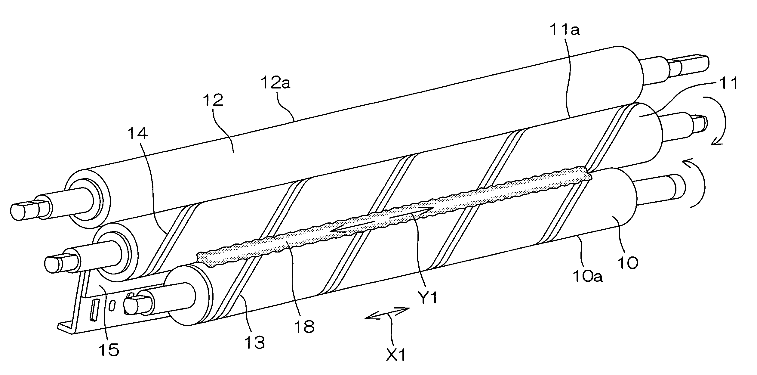
The present invention provides a liquid developing unit and an image forming apparatus that can evenly supply a liquid toner. The liquid developing unit includes a pick-up roller and an application roller with spiral-shaped grooves that guide the liquid toner in opposite directions, preventing uneven distribution on the application roller. The pick-up roller and application roller can rotate in opposite directions or the same direction, and the spiral grooves can be twisted in the same or opposite directions. This ensures that the liquid toner is supplied to the application roller evenly, improving the quality of the images.

Problems solved by technology

However, in the foregoing apparatus, since the liquid toner in the tank is drawn only by means of the application roller, and the drawn liquid toner needs to be leveled so that the amount thereof is even on the circumferential surface, it is disadvantageously hard to supply the developing roller with the liquid toner.
However, applying the invention disclosed in the above-identified Japanese Unexamined Patent Publication to a liquid developing unit including such a pick-up roller for supplying the liquid toner to the application roller causes the following problem.
As a result, the liquid toner fails to be evenly supplied along the axial direction of the application roller.
Accordingly, it is impossible to supply the liquid toner evenly along the axial direction of the developing roller and the photosensitive member, which results in degraded quality of the image transferred from the photosensitive member to the paper.

Method used


Image

  • Liquid developing unit and image forming apparatus including the same
  • Liquid developing unit and image forming apparatus including the same
  • Liquid developing unit and image forming apparatus including the same

Examples


Embodiment Construction

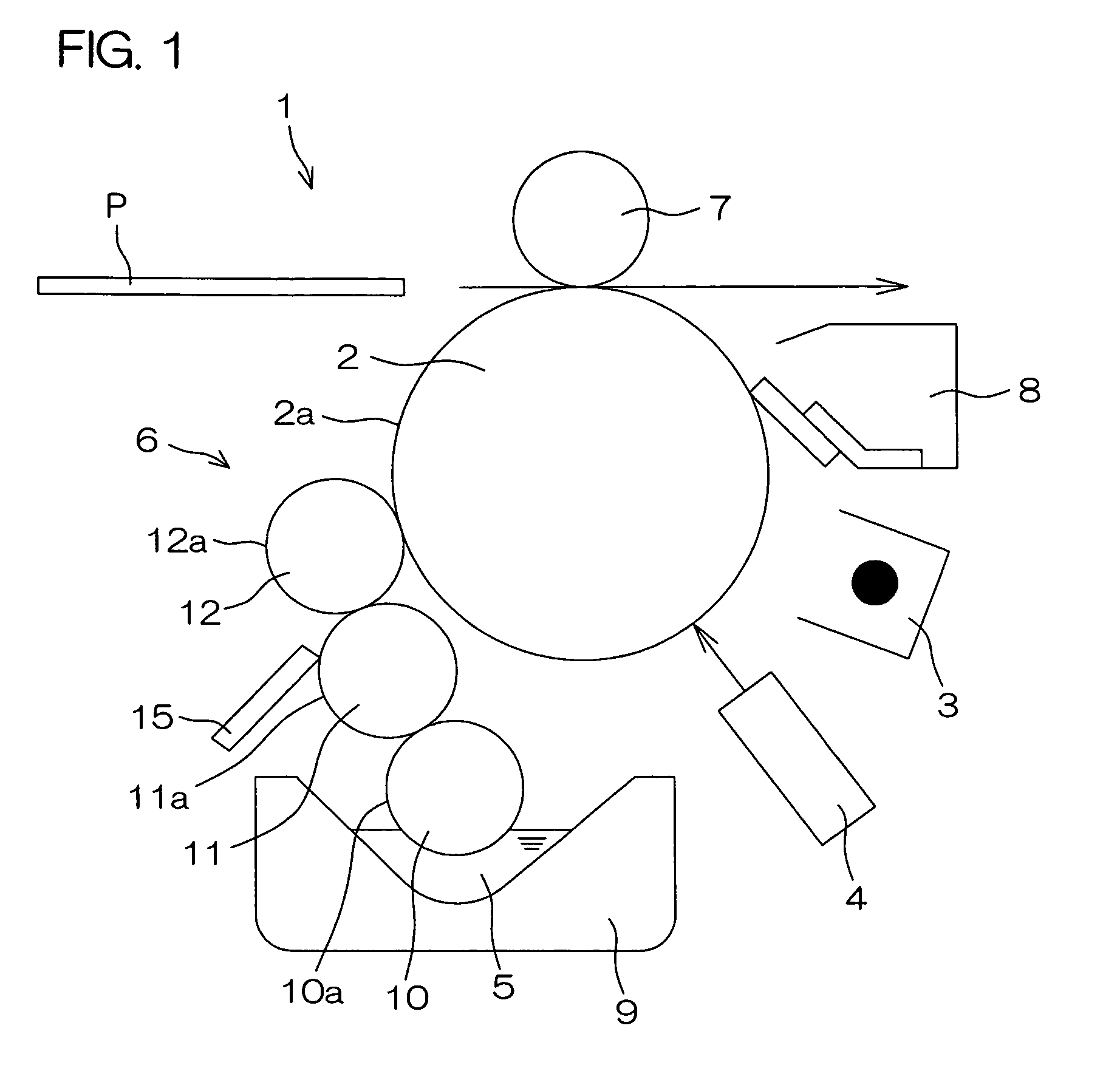
[0019]FIG. 1 is a diagram showing a schematic arrangement of an image forming section 1 provided in a printer according to one embodiment of the present invention. A nonvolatile liquid toner with high viscosity is used as a developing agent in this embodiment.

[0020]Referring to FIG. 1, the image forming section 1 includes a cylindrical photosensitive drum 2, a charging device 3 for electrically charging a circumferential surface 2a of the photosensitive drum 2, an exposure device 4 for forming an electrostatic latent image by irradiating an optical image based on image data onto the circumferential surface 2a of the photosensitive drum 2, a developing unit 6 for forming a toner image by supplying a liquid toner 5 to the circumferential surface 2a of the photosensitive drum 2, a transfer roller 7 for transferring the toner image formed on the circumferential surface 2a of the photosensitive drum 2 to a paper sheet P, and a cleaning device 8 for removing the liquid toner 5 remaining o...


PUM


Abstract

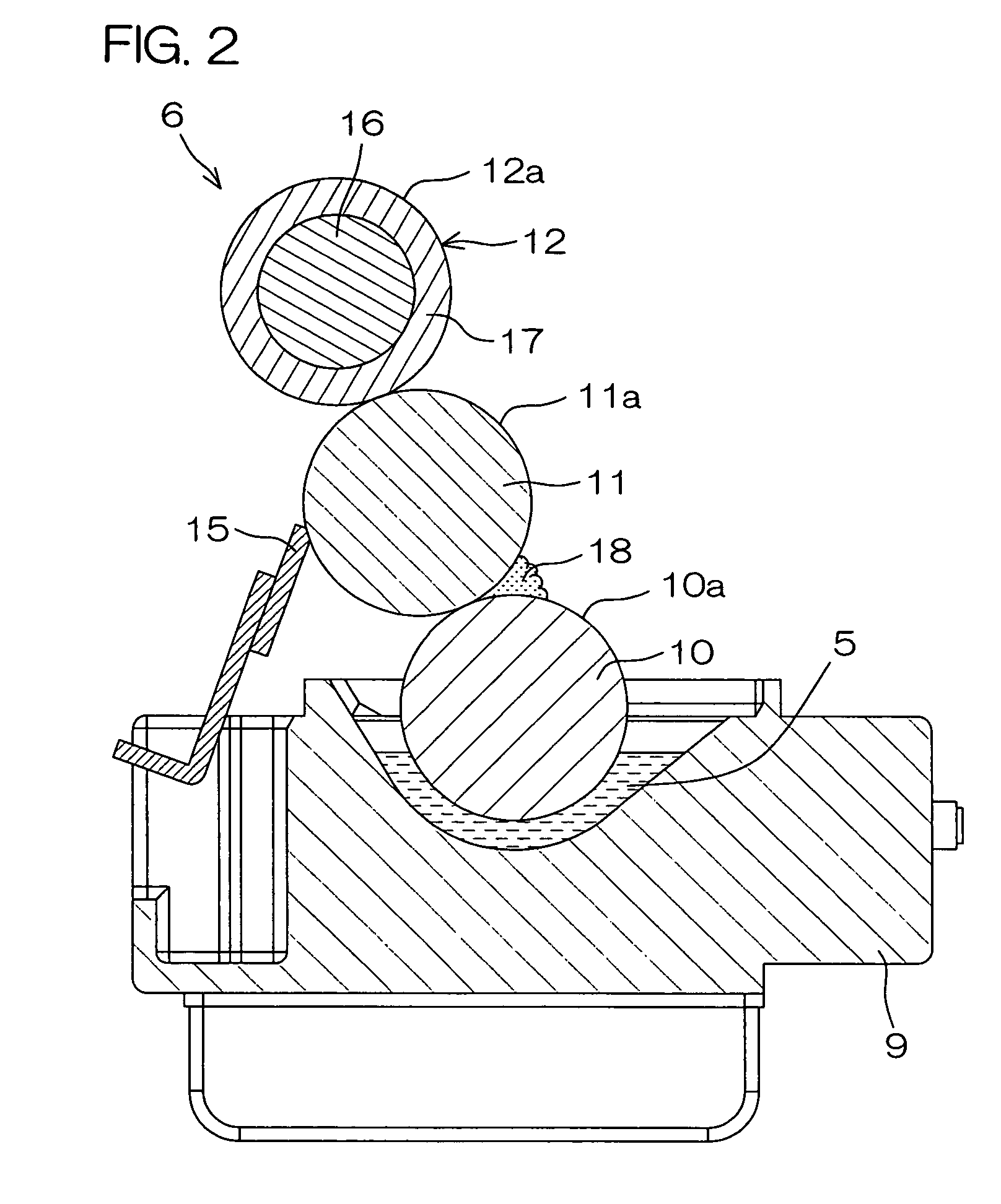
Disclosed is a developing unit 6 including a tank containing a liquid toner, a pick-up roller 10 for drawing the liquid toner from the tank, an application roller 11 whose circumferential surface 11a is supplied with the liquid toner by the pick-up roller 10, and a developing roller 12 whose circumferential surface 12a is applied with the liquid toner by the application roller 11. The pick-up roller 10 and the application roller 11 are arranged in parallel to each other and circumferential surfaces 10a, 11a thereof are in contact with each other. The circumferential surfaces 10a, 11a of the pick-up roller 10 and the application roller 11 are formed with a plurality of grooves 13, 14, respectively, which extend continuously in the axial direction X1.

Description

BACKGROUND OF THE INVENTION[0001]1. Field of the Invention[0002]The present invention relates to an image forming apparatus including copiers, printers, facsimiles and the like, specifically, to an image forming apparatus in which development is accomplished by the liquid developing unit. Also, the present invention relates to the liquid developing unit.[0003]2. Description of Related Art[0004]An electrophotographic image forming apparatus includes, for example, an image forming apparatus comprising a liquid developing unit that supplies a liquid toner to a photosensitive drum on which an electrostatic latent image is formed so as to develop the electrostatic latent image. This liquid developing unit includes a developing roller for supplying the liquid toner to the photosensitive drum. The liquid toner in a tank is drawn by an application roller, and at the same time, the toner on the circumferential surface of the application roller whose amount is regulated by a doctor blade is s...

Claims


Application Information

Patent Timeline
Patent Type & Authority Patents(United States)
IPC IPC(8): G03G15/10
CPCG03G15/104
Inventor ODA, TOMOYUKIMURASE, KOJIUEDA, HIROYUKITAKENAKA, HIDENORIHOBO, JUNPEI
Owner KYOCERA DOCUMENT SOLUTIONS INC
Learn More