
Capacitive pressure sensor

a capacitive pressure sensor and capacitance variation technology, applied in the field of sensors, can solve the problems of complex design disclosed in park, increased number of parts, and general incompatibility of conventional sensing membranes with a wide range of media, so as to improve reliability, simplify manufacturing and assembly process, and reduce cost

Inactive Publication Date: 2008-06-10
DELPHI TECH INC
View PDF13 Cites 43 Cited by
  • Summary
  • Abstract
  • Description
  • Claims
  • Application Information

AI Technical Summary

Benefits of technology

[0005]A sensor in accordance with this invention provides a configuration that permits a simplified manufacturing and assembly process, overcoming the complicated and complex manufacturing process described in the Background. Additionally, embodiments of the present invention provide a configuration with a reduced number of parts—fewer parts that can fail thereby improving reliability. Additionally, the simplified configuration provides for a less expensive sensor. Further, a sensor according to the present invention embodies a mechanization that provides for greater flexibility is constructing the sensing diaphragm for different pressure ranges, media compatibility and material selection, all of which improve the cost effectiveness of the sensor.

Problems solved by technology

The design disclosed in Park, however, is rather complicated and includes an increased number of parts.
Moreover, these sensors also have a shortcoming insofar as not being able to effectively seal high pressures.
In addition, conventional sensing membranes are generally not compatible with a wide range of media (i.e., the fluid whose pressure is being sensed).

Method used


Image

  • Capacitive pressure sensor
  • Capacitive pressure sensor
  • Capacitive pressure sensor

Examples


Embodiment Construction

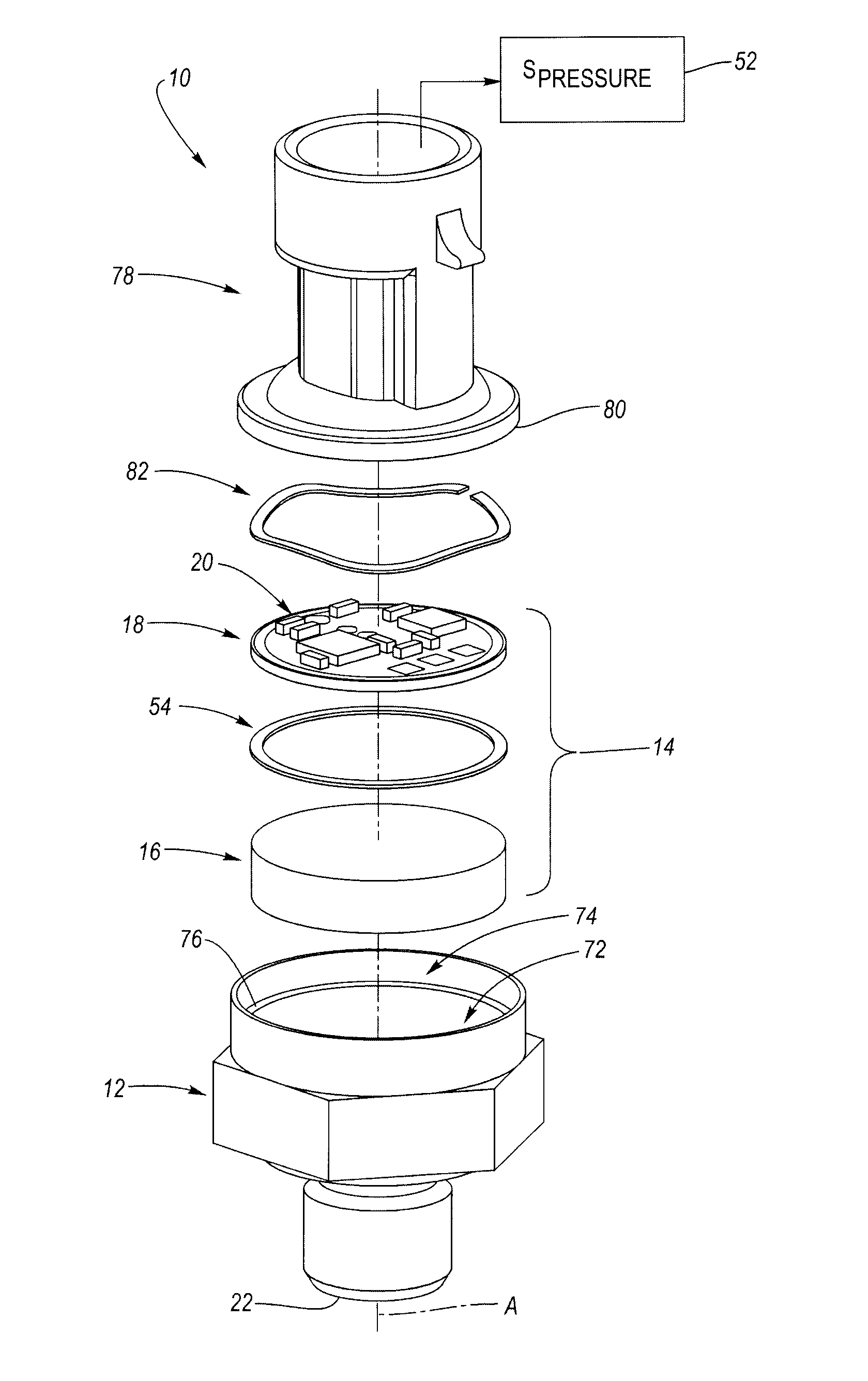
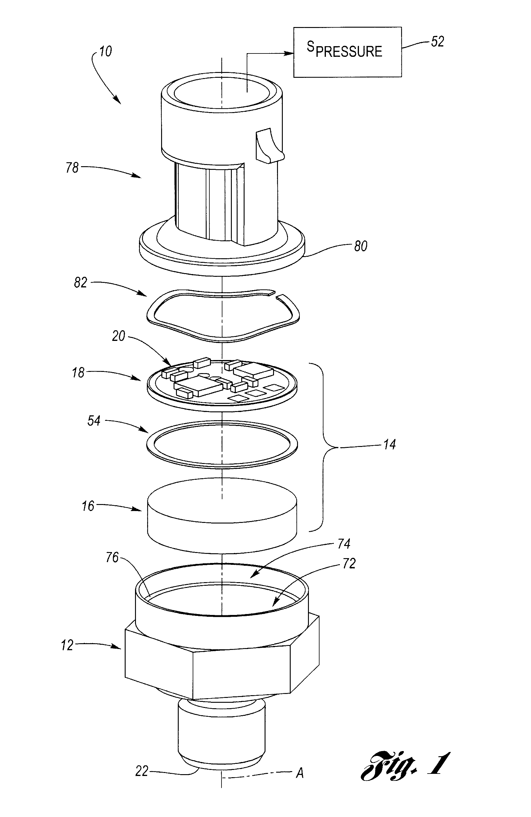
[0028]FIG. 1 shows a capacitive pressure sensor 10 in accordance with the present invention in an exploded, non-assembled state. Sensor 10 is formed of a plurality of components which, when assembled, fit together in a concentrically aligned manner along a main longitudinal axis, designated axis “A” in FIG. 1. Sensor 10 includes a base-port 12, a transducer 14 having (i) a diaphragm 16 and a (ii) sensing electrode body 18, and a pressure signal generating circuit 20. The invention features a sensor with a configuration having a reduced number of parts, which improves cost effectiveness and decreases the complexity of manufacturing.

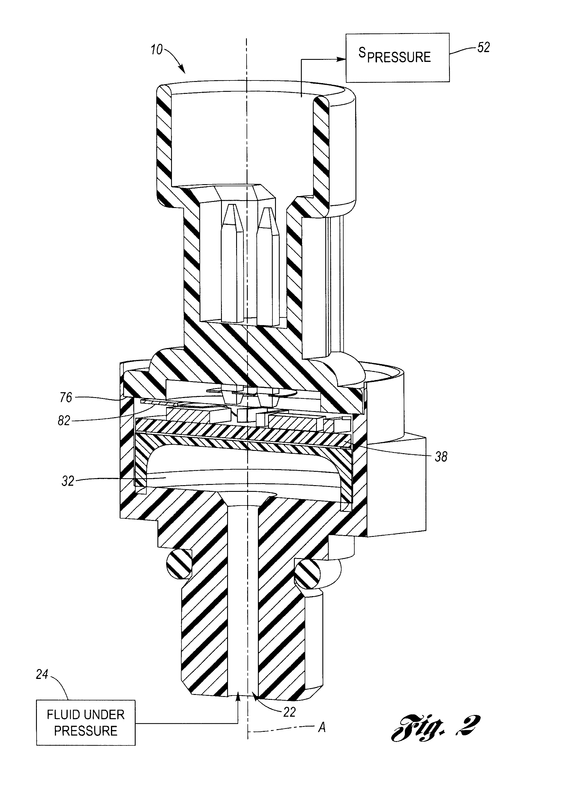
[0029]FIG. 2 is a cross-sectional view of sensor 10 in an assembled state, which illustrates the axial compactness of the assembly. From an operational point of view, base port 12 has an opening 22 configured to receive a fluid, designated by block 24, under pressure having a value that may vary over time. This is the “input.” The sensor 10, more specifica...


PUM


Abstract

A capacitive pressure sensor includes a electrically conductive, generally piston shaped diaphragm with a flexible base wall configured to deflect under pressure. The diaphragm is generally U-shaped in cross section. The base wall includes an upper, flat sensing surface which acts as a capacitive electrode. The diaphragm further includes a step around a radially-outermost perimeter which is elevated from the flat sensing surface. A sensing electrode body is located on top of the step and creates a capacitive sensing cavity between the sensing surface and the bottom surface of the electrode body. On the bottom surface of the electrode body is formed a center, circular electrode and a ring electrode that surrounds the center electrode. The center electrode and the sensing surface form a variable capacitor which changes with pressure and the ring electrode and the sensing surface form a reference capacitor. A circuit determines a differential capacitance between the variable capacitor and the reference capacitor and generates a pressure signal indicative of the fluid pressure applied to the diaphragm. A spring ring holds the sensing electrode body against the diaphragm when assembled. The diaphragm can be a machined metal part or a sheet metal cup. The sensing electrodes and signal generating circuit can take the form of a hybrid circuit.

Description

TECHNICAL FIELD[0001]The invention relates in general to sensors, and more particularly, to a capacitive pressure sensor.BACKGROUND OF THE INVENTION[0002]In the automotive industry, it is frequently necessary to know the pneumatic or hydraulic pressure in a container or along a pressure line. Current technologies for pressure measurement sensors include piezoresistive technology implemented using thick film, thin film and MEMS, which involve, for example, building a strain gage on the top surface of a sensing membrane.[0003]Additionally, it is known to employ capacitive technology, for example on MEMS and / or discrete membranes, as seen by reference to U.S. Pat. No. 5,656,780 entitled CAPACITIVE PRESSURE TRANSDUCER WITH AN INTEGRALLY FORMED FRONT HOUSING AND FLEXIBLE DIAPHRAGM issued to Park (“Park”). Park discloses a pressure transducer that includes a reference capacitor electrode and a variable capacitor electrode, both of which are electrically connected to a circuit. The variabl...

Claims


Application Information

Patent Timeline
IPC IPC(8): G01L9/12
CPCG01L9/0072
Inventor LIN, YINGJIEURQUIDI, CARLOS A.ROMO, FRANCISCO
Owner DELPHI TECH INC
Learn More