
Method to convey uplink traffic information

a traffic information and uplink technology, applied in the field of communication systems, can solve the problems of wasting air link resources, requiring more than a few bits, and each transaction is generally slow, and achieve the effect of reducing the propagation of errors

Active Publication Date: 2008-06-03
QUALCOMM INC
View PDF14 Cites 36 Cited by
  • Summary
  • Abstract
  • Description
  • Claims
  • Application Information

AI Technical Summary

Benefits of technology

[0033]The present invention is directed to methods and apparatus for making traffic channel resource allocation requests. Requests may include information such as the number of transmission units required and / or the priority level of data to be transmitted using the requested units. Requests may be of several types. Requests of different types are arranged in groups in some embodiments. Incremental, e.g., relative requests may be made within a group of request. However, groups of requests are interpreted in many embodiments independently, with absolute request values being used to reduce the propagation of errors in tracking request status from one group of requests to the next. Groups of requests including multiple requests may be transmitted on a periodic basis or according to some pre-selected schedule. In some embodiments, groups of requests are transmitted in time periods under 98 milli seconds (ms) in duration to ensure accurately and timely uplink status information.
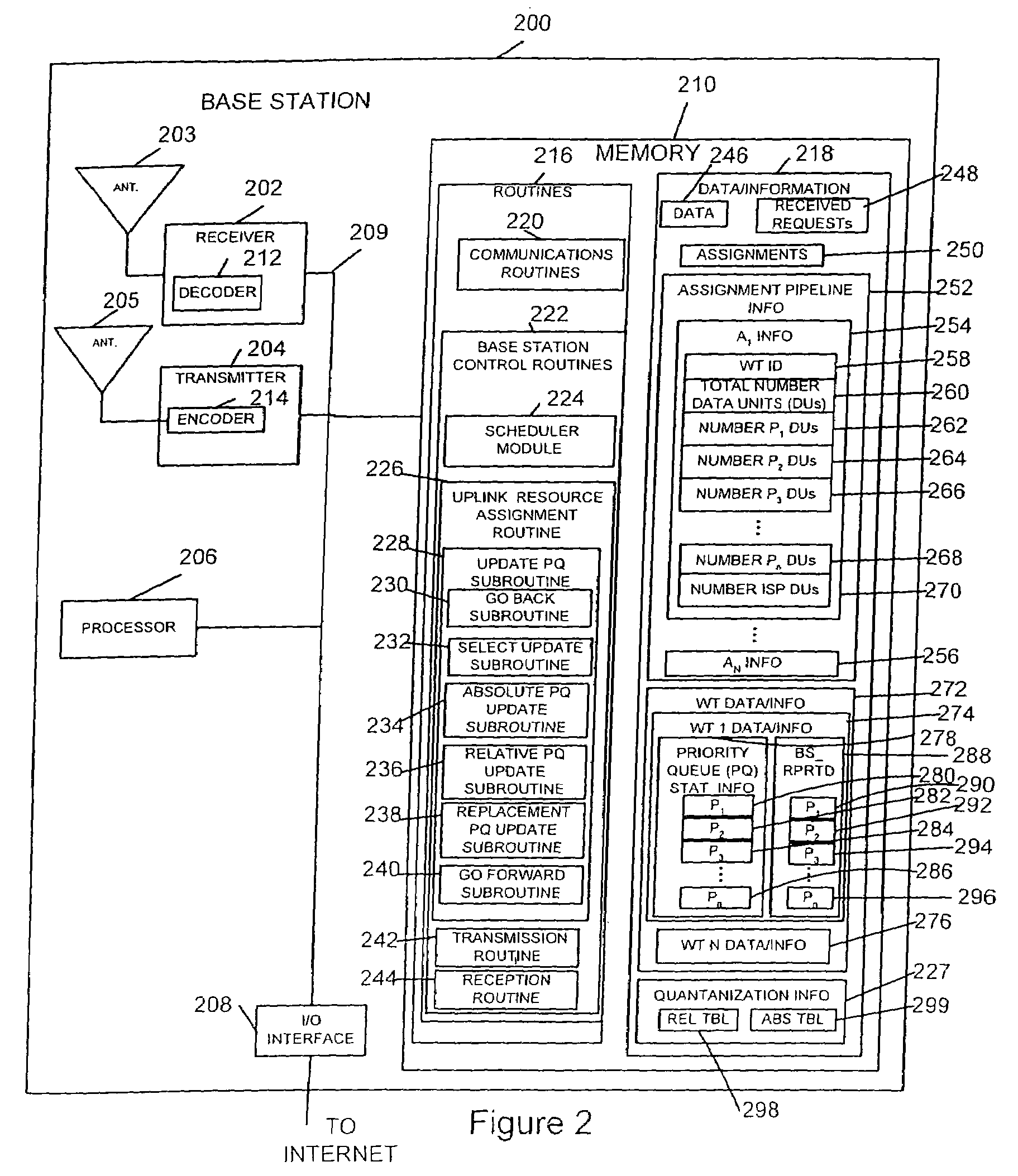
[0034]In accordance with the invention, the requests transmitted in each group of requests (GOR) over time by a wireless terminal (WT), e.g., mobile node, end node or mobile station, can be interpreted by the receiving base station (BS) without knowledge of the requests made in another GOR. Within each GOR, in one exemplary embodiment, the BS can interpret the request made in the first (0th) request unit by itself. This is because the first request in each group of requests is transmitted in the exemplary embodiment as an absolute value which does not depend on previously transmitted requests. Subsequent requests in the group of requests may be transmitted as relative values, e.g., values which are to be interpreted as a function of some previously transmitted request value and / or as a function of assignment information which corresponds to grants of previous requests. A relative request value may be, e.g., a request for an incremental number of transmission data units corresponding to the priority level associated with the associated request. In the exemplary embodiment, the first time data units corresponding to a particular priority level are requested, the request is made using an absolute value. In some, but not all implementations, subsequent requests made for transmission units of the same priority level in the same GOR are communicated using relative values. In some implementations the number of relative request values in a GOR is more than the number of absolute request values thereby leading to efficient use of the limited request communications resource. The start of each GOR allows the BS to updates its counters, e.g., queue information, using absolute values and thereby correct for various errors which may accumulate due to the use of relative request values and / or the failure to receive all transmitted requests. All BS counters need not be reset at the start of each GOR. Thus, in the case of relative requests, the relative request values included in such requests are normally interpreted by the BS based on one or more of the requests made in preceding request units of the same group of requests.
[0036]In some embodiments, requests are formed based on the WT's actual Q-stats msQ. In addition to being based on msQ, a request can also be based on msBsQ, and / or preceding requests in the same group of requests. Relative request values are generated in this manner in some embodiments. Periodically and / or frequently requests are formed without basing them on msBsQ. The values used in such requests are normally absolute values, e.g., values which indicate a full actual count of the number of transmission data units desired for a particular priority level as opposed to an incremental number of desired data units, the number of data units desired beyond the number already requested. The use of absolute values facilitates quick synchronization between WT and BS understanding of Q-stats in case of the loss of requests or assignments due to channel errors.
[0039]Tracking bsQ at the WT (through the variable msBsQ at WT), and the ability to be able to report WT's traffic information (msQ) relative to msBsQ, gives the WT great flexibility in constructing uplink requests. In one embodiment, after reporting absolute traffic information about priority group A in one request, in the next request the WT can decide to report absolute traffic information about another priority group B instead of reporting relative traffic information about priority group A. Such flexibility may not available in a scheme where WT reports its absolute traffic information or its quantized version (based on msQ) without recourse to msBsQ. In another embodiment, the WT can split reporting of traffic information about a priority group into multiple requests in a way that adds robustness to the requests against channel errors. For example, 15 frames of priority group 3 can be reported as 8 frames in one request and 7 frames in the next request (instead of say 12 frames in one request and 3 frames in next request, or simply 15 frames in one request). This way, if the first request is lost the second can still provide a good idea of MS's traffic information. Again, this may not be possible with a scheme based solely on reporting absolute traffic information or its quantized version.
[0042]In some embodiments, a request can carry information regarding non-zero count (or its quantized version) of frames of a single stream priority, where this stream priority need not be the highest stream with non-zero frames. The count reported in such a case is an absolute count of the number of frames. Here, the WT has great flexibility in picking the priority that it chooses to report.

Problems solved by technology

Each transaction is generally slow and will require more than a few bits.
Intervals of unused transmission time between the establishment of the link and the termination of the link represents wasted air link resources.
With packet switch wireless systems, e.g. an OFDM system, this circuit switch approach is inefficient, as the wireless terminal generally do not need the air link resource for long contiguous segments, but rather need short durations, e.g., flash intervals.
In addition, it is inefficient, in packet switch systems to be constantly have to renegotiate for a small amount of air link resource, as the overhead signaling becomes significant in relation to the amount of air link resource actually used for traffic.
This approach has a delay effect problem.
There is a delay between when the wireless terminal transmits a request for uplink air link resources, and the time that a base station receives and processes the request.
There is also a delay between the time when the base station generates and transmits the assignment and the wireless terminal receives and recognizes the assignment.
These delays create misunderstandings between the base station and the wireless terminal resulting in wasted air link resources, unnecessary additional requests, and unnecessary additional assignments.
This problem of lack of understanding between the base station and wireless terminal becomes more complicated and new problems are created when multiple levels of priorities are considered.
It is inefficient to transmit that requested data units are no longer needed.
This dropping of requested data units unbeknown to the base station can result in misunderstanding and unnecessary wasted assignments by the base station.
Also, some requests may be lost due to transmission errors, and there are trade-offs between whether to transmit another request immediately or whether to wait, since the wireless terminal does not know whether the base station never received the request or has not transmitted the assignment because of other higher priorities competing for the air link resource.
This can also result in misunderstandings between the base station and the wireless terminal.

Method used


Image

  • Method to convey uplink traffic information
  • Method to convey uplink traffic information
  • Method to convey uplink traffic information

Examples


Embodiment Construction

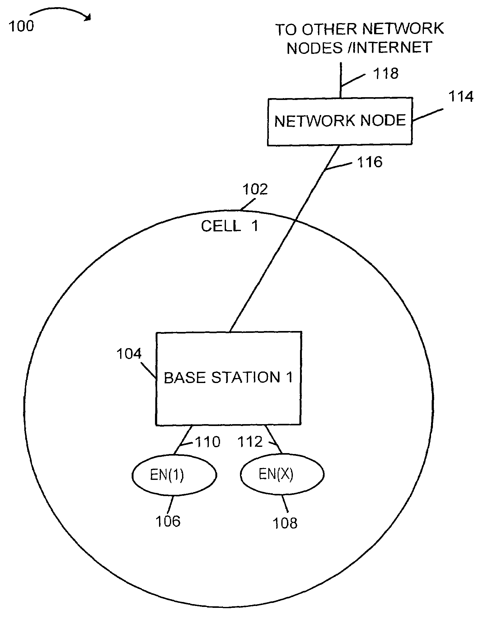
[0046]FIG. 1 shows an exemplary communication system 100 implemented in accordance with the present invention which includes a plurality of cells, such as cell 1102 which is shown.

[0047]Cell 1102 includes a base station (BS), base station 1104, and a plurality of wireless terminals, e.g., end nodes (ENs), EN(1) 106 and EN(X) 108. EN(1) 106 and EN(X) 108 are coupled to BS1104 via wireless links 110, 112, respectively. System 100 also includes a network node 114 which is coupled to BS1104 via network link 116. Network node 114 is also coupled to other network nodes, e.g., other base stations, AAA server nodes, intermediate nodes, routers, etc. and the Internet via network link 118. Network links 116, 118 may be, e.g., fiber optic cables. Each end node, e.g. EN(1) 106, may be a wireless terminal including a transmitter as well as a receiver. The wireless terminals, e.g., EN(1) 166, may move through system 100 and may communicate via wireless links with the base station in the cell in w...


PUM


Abstract

Methods and apparatus for a Wireless Terminal (WT) to convey uplink traffic information, e.g., uplink channel resource requests, to a Base Station (BS) are described. Uplink transmission resources are requested for data corresponding to different priority levels. The WT keeps track of the BS's understanding of WT traffic through the use of a first queue which keeps track of the BS's estimate of WT's uplink queue status for different priority levels by following the same procedure the BS uses to update its estimate of WT queue status. The WT uses this tracked information along with actual traffic information it maintains in a second set of queue information to form uplink traffic channel requests to be transmitted to the BS. Methods used by the BS to interpret uplink traffic channel requests from WTs are also described. The BS maintains its own queue of requests and corresponding priority information for individual WTs.

Description

RELATED APPLICATIONS[0001]The present application claims the benefit of U.S. Provisional Patent Application Ser. No. 60 / 415,787 filed Oct. 3, 2002 which is hereby expressly incorporated by reference.FIELD OF THE INVENTION[0002]The present invention relates to communications systems and, more particularly, methods and apparatus to generate and convey uplink traffic information, e.g. requests and assignments for uplink air link resources, between wireless terminals and a base station in a cellular communications network.BACKGROUND[0003]In a cellular wireless system, a service area is divided into a number of coverage zones generally referred to as cells. Each cell may represent the wireless coverage area for a base station. Wireless terminals, including a wide range of mobile devices such as, e.g., cell phones and other mobile transmitters such as personal data assistants with wireless modems, may communicate with the base station via wireless links while located within the base stati...

Claims


Application Information

Patent Timeline
Patent Type & Authority Patents(United States)
IPC IPC(8): H04J3/00H04B7/212H04J3/16H04L12/56H04W4/24H04W8/24H04W28/14H04W72/00H04W72/10H04W72/12
CPCH04W72/10H04W72/1242H04W8/245H04W28/14H04W72/0413H04W72/1268H04W72/21H04W72/56H04W72/569
Inventor DUGAD, RAKESHLI, JUNYI
Owner QUALCOMM INC
Learn More