
Apparatus and methods for stenciling an image

a technology of image stenciling and image, applied in the field of computer graphics applications, can solve the problems of inability to use, remove more color, limited value of partial masks that are available in current graphics applications, etc., and achieve the effect of accurate control of image editing

Active Publication Date: 2008-06-03
3D SYST INC
View PDF163 Cites 38 Cited by
  • Summary
  • Abstract
  • Description
  • Claims
  • Application Information

AI Technical Summary

Benefits of technology

This approach enables precise control over image editing, maintaining specified opacity and preventing excessive color change or removal within protected regions, even with overlapping strokes, while preserving real-time interactivity and minimizing artifacts.

Problems solved by technology

Partial masks that are available in current graphics applications are of limited value where paint strokes overlap.
It is not possible for a user to specify that an initial version of a selected region of an image be maintained at a specified opacity in any subsequent composite.
Similarly, overlapping erase strokes within a partially-masked region may result in a removal of more color than is desired by the user, since overlapping erase strokes in the selected region will eventually reduce the opacity of the original layer below the desired minimum.
Furthermore, current methods of blending individual paint strokes into an image may result in undesired artifacts.
Overlapping portions at the ends of segments of an individual paint stroke are blended twice, causing undesired artifacts.

Method used

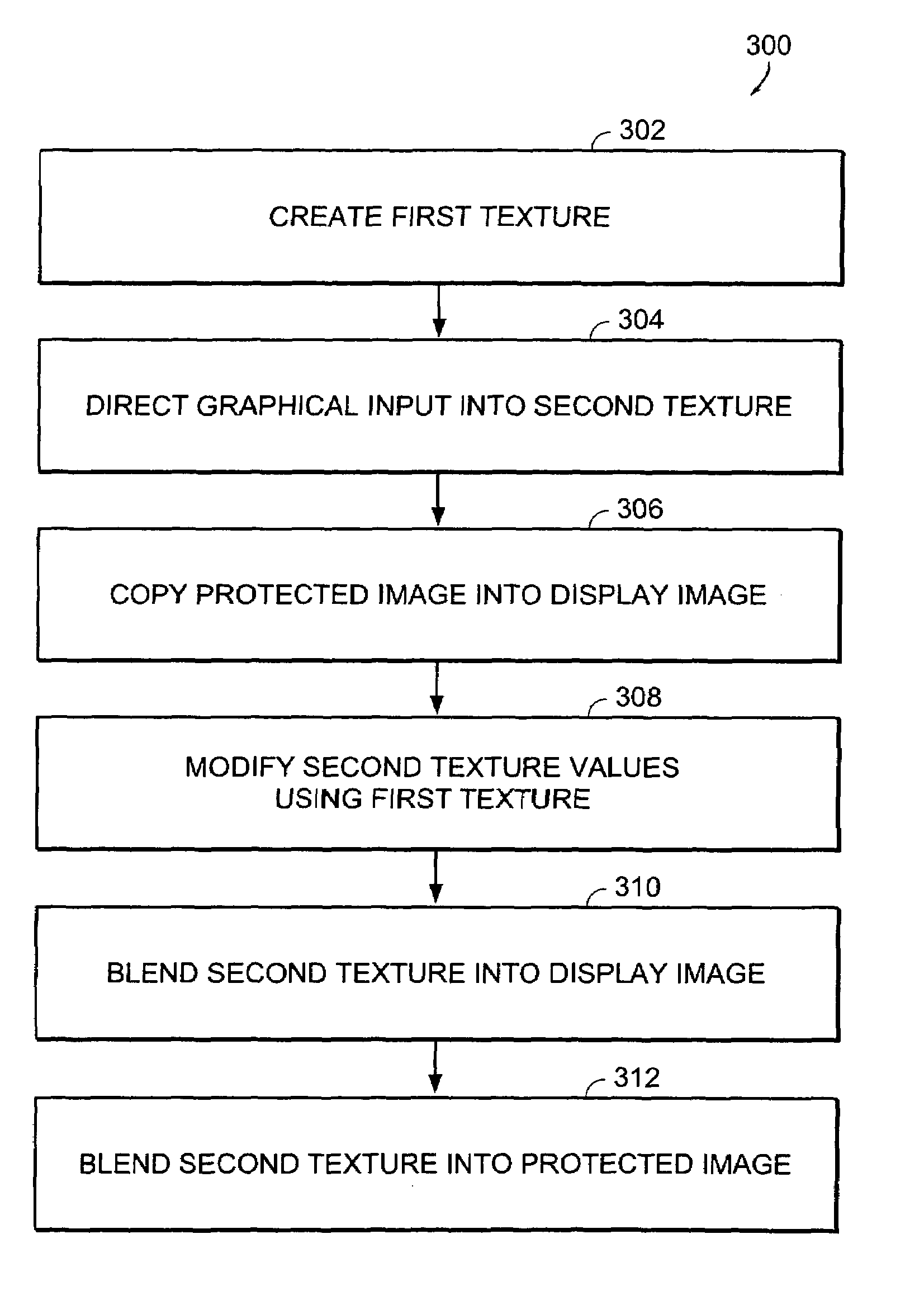
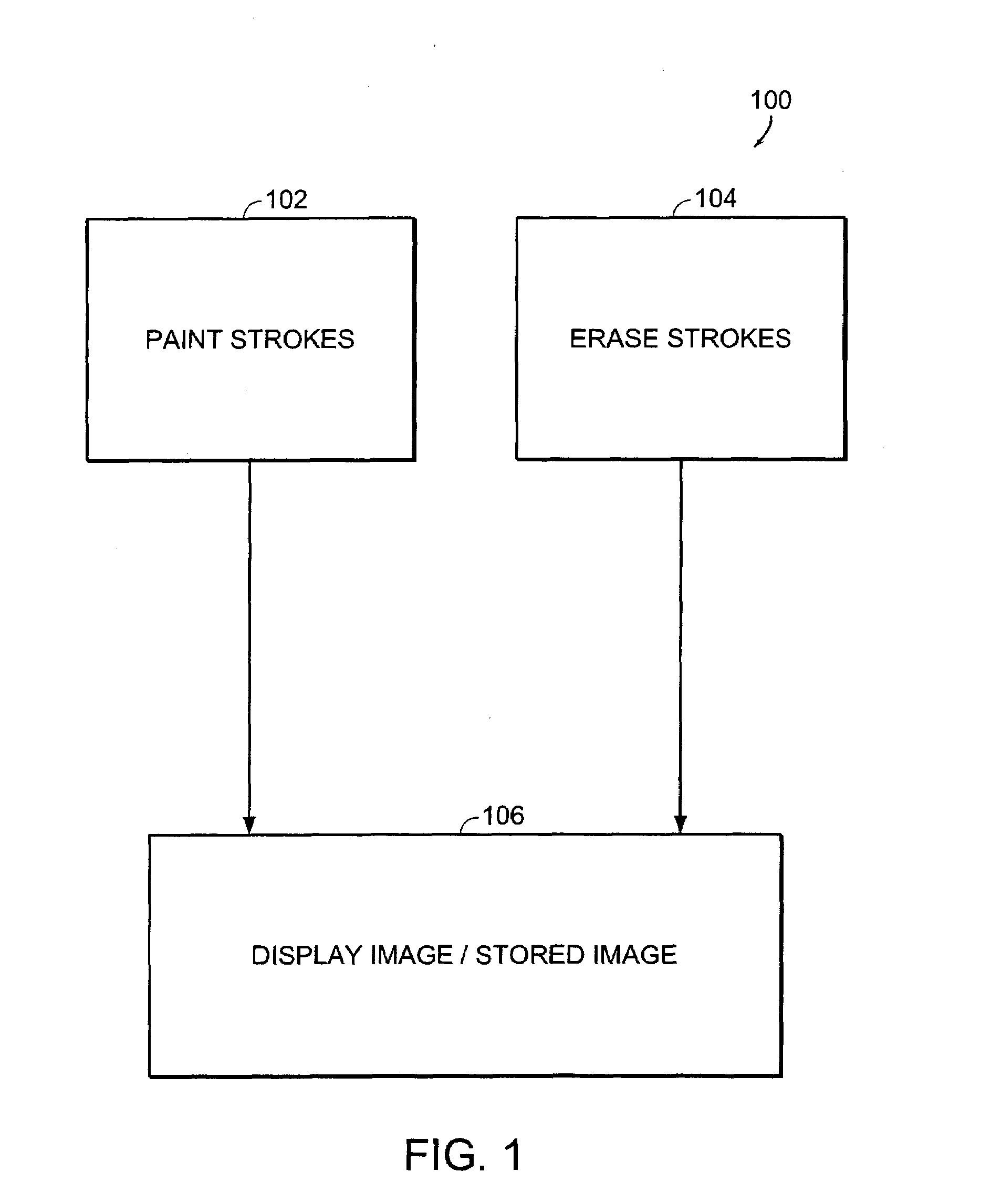
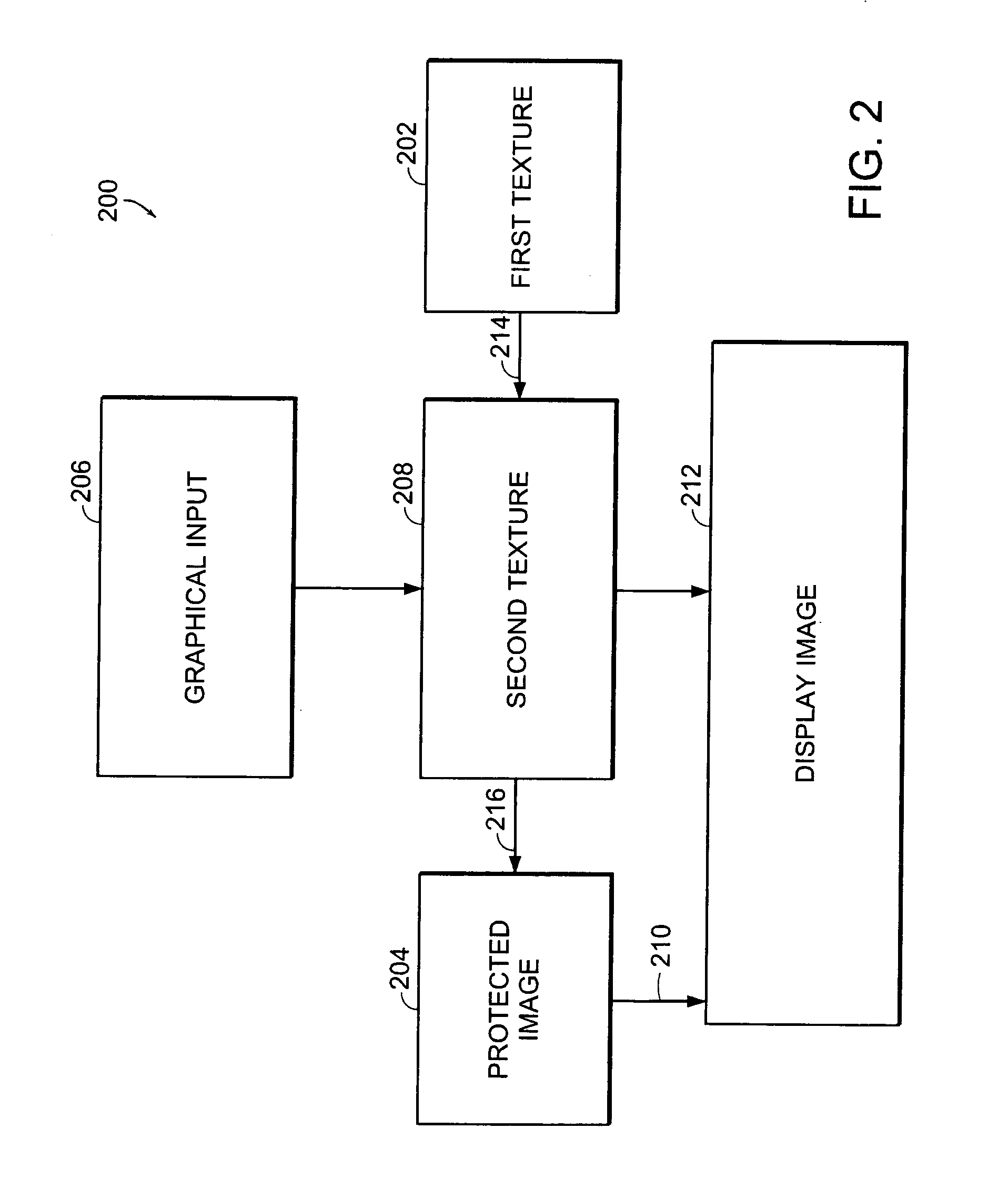

Image

  • Apparatus and methods for stenciling an image
  • Apparatus and methods for stenciling an image
  • Apparatus and methods for stenciling an image

Examples


Embodiment Construction

[0057]In general, the invention relates to methods for protecting a selected region of an image from subsequent editing. More specifically, the invention provides methods of specifying a maximum amount by which one or more selected portions of an image are allowed to change during the course of a series of brush strokes.

[0058]As used herein, a brush stroke is an operation performed on one or more pixels of an image. Brush strokes include, for example, paint strokes, erase strokes, pencil strokes, pen strokes, lines, characters, and text.

[0059]Each brush stroke is divided into segments that link positions of a graphical interface device, such as a stylus or other painting tool. The positions are recorded at successive frames as the user moves the graphical user interface device in real space, and, preferably, while the user views a graphical rendering of the image upon which the user is applying the brush stroke. Each brush stroke may be represented as having a skeleton made up of a ...


PUM


Abstract

The invention provides methods of protecting selected regions of an image from subsequent modification during the operation of a graphics application. The methods allow a user to select a region of an image to protect, and to assign a level of protection to the selected region. Subsequent brush strokes in the region are then attenuated according to the assigned level of protection and blended into the image without artifacts caused by overlapping strokes. The invention also provides a method of blending individual strokes into a texture without segmentation artifacts.

Description

RELATED APPLICATIONS[0001]This application is related to the commonly-owned U.S. patent application entitled, “Apparatus and Methods for Texture Mapping,” by Levene et al., filed under Ser. No. 10 / 697,548, on even date herewith, the text of which is hereby incorporated by reference in its entirety.FIELD OF THE INVENTION[0002]This invention relates generally to computer graphics applications. More particularly, in certain embodiments, the invention relates to image editing functions in computer graphics applications.BACKGROUND OF THE INVENTION[0003]Certain computer graphics applications include a stenciling function for protecting part of an image from subsequent paint strokes. A stenciling function allows a user to select a region of the image to protect, such that subsequent paint strokes falling within the selected region are not blended into the image.[0004]A stenciling function may also allow a user to apply a partial mask to a selected region, such that a subsequent paint strok...

Claims


Application Information

Patent Timeline
Patent Type & Authority Patents(United States)
IPC IPC(8): G09G5/02G09G5/00
CPCG06T11/60G06T15/503
Inventor LEVENE, JONATHANHANDLEY, JOSHUAITKOWITZ, BRANDON
Owner 3D SYST INC
Learn More